SEAPERCH II MODULE 3 PART 2:
SeaPerch Controller Box with Gripper Pump Switch
Make a soft-robotic gripper for the SeaPerch underwater robot, and control it from the SeaPerch controller.
This project builds on the Soft-Robotic Grippers module, adding a submersible pump that closes the gripper. The gripper releases when the pump is depowered. The pump wiring fits with the existing wiring protocol, making use of 2 spare wires in the ethernet cable. Build a new robust controller or adapt the controller sold by RoboNation. Video at https://youtu.be/j3IgM_aeV5s
How it works
This project builds on the Soft-Robotic Grippers module, adding a submersible pump that closes the gripper. The gripper releases when the pump is depowered. The pump wiring fits with the existing wiring protocol, making use of 2 spare wires in the ethernet cable. Build a new robust controller or adapt the controller sold by RoboNation. Video at https://youtu.be/j3IgM_aeV5s
Who can build it: The activities here are recommended for middle to high school students.
Knowledge and skills developed in this project:
- Hand fabrication including measuring, marking, drilling and assembly
- Electronics fabrication including wiring and soldering
Safety: The fabrication activities include wiring, soldering, drilling, and hand assembly. Tool and shop safety measures include following directions on any tools and materials, wearing personal protective equipment (PPE) such as safety goggles, maintaining an orderly working space, and working with adult supervision.
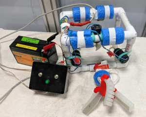
Full system: SeaPerch with powered gripper, controller, battery
Do-It-Yourself (DIY) controller

Modified RoboNation controller
Project tools and materials for *DIY Robust Controller* with gripper pump and switch
Project tools and materials for *DIY Robust Controller* with gripper pump and switch
See detailed list of materials and tools, with links to sources, below.
Materials
- Completed SeaPerch
- Soft-Robotic Grippers for SeaPerch
- Submersible pump, 12 V, impeller
- Clear flexible tubing, 1/8″ ID x 3/16″ OD, either PVC or silicone, as used in Soft-Robotic Grippers project
- Electronics box, ~4.5” x 3.5” x 2.2”
- Ethernet cable connector (RJ45), panel mount
- 2 toggle switches, DPDT
- 2 push button switches, SPDT
- 1 push button switch, SPST
- Black and red stranded wire, 24 AWG
- Other colors of stranded wire, or wire from a piece of ethernet cable
- Wire nuts
- Piece or wood or acrylic to build circuit on, ~ 5” x 8”
- 2 conductor cable, 18 AWG, such as speaker wire
- 2 Alligator clip ends, red and black
Tools
- Mechanical drawings
- Soldering station (Iron, brass sponge, solder, tip cleaner)
- Screwdriver – Philips head
- Screwdriver, flat blade, small (for electronics)
- Wire cutter
- Wire strippers
- Needle-nose pliers
- Alligator clips
- Hand drill or drill press
- Step drill bit set with
- Marking punch (may come with step drills)
- Drill bit
| Qty | Cost each | Item | Source (use Amazon links or find similar parts from other vendors) |
| 1 | Completed Sea Perch | Basic SeaPerch Build Guide | |
| 1 | $12/ 3 pcs | Submersible pump, 12 V, impeller | https://www.amazon.com/Gikfun-2-5V-6V-Submersible-Silicone-EK1374/dp/B0957BS936 |
| Clear flexible tubing, 1/8″ ID x 3/16″ OD, either PVC or silicone, as used in Soft-Robotic Grippers project | https://www.amazon.com/gp/product/B09DYWL124/ | ||
| Fittings for PVC tubing | |||
| Drawings for controller box and build board, and wiring diagrams | Mechanical drawings and electrical schematics | ||
| 1 | $10 ea | Controller Box (electronics project box, plastic, 4.5” x 3.5” x 2.2”) | https://www.amazon.com/dp/B0D5658VRT |
| 1 | $10 /2 pcs | Ethernet cable connector (RJ45), Panel mount | https://www.amazon.com/dp/B0C85F5BSD |
| 2 | $10/ 6 pcs | Toggle switch, DPDT, (On)-Off-(On), miniature | https://www.amazon.com/dp/B07VK46JQ3 |
| 2 | $9/ 5 pcs | Push button switch, SPDT, NO and NC, miniature | https://www.amazon.com/dp/B079D923V9 |
| 1 | $8/ 10 pcs | Push button switch, SPST, green | https://www.amazon.com/DIYhz-Momentary-Button-Switch-Round/dp/B08B1ND6GL/ |
| 1 | $15/ 6 rolls | Hook up wire, stranded, 24 AWG, black red and other colors | https://www.amazon.com/dp/B073QHZK55 |
| 1 | wire from a piece of ethernet cable | 12” piece of ethernet cable, sheath removed | |
| 8 ft | $10/ 50’ | Speaker wire, 18 AWG | https://www.amazon.com/Elecan-Gauge-Pro-Conductors-Transparent-Speakers-Gold/dp/B0CJR6QP4M |
| 2 | $12/ 20 pcs | Alligator clip ends, 1.8” long, red and black | https://www.amazon.com/Alligator-DROK-Electrical-Protective-Insulation/dp/B07B2R3GCD |
| 2 | $10 / many | Wire nuts, medium | https://www.amazon.com/330-Pcs-Wire-Connectors-Nuts/dp/B0B8CVN2NN |
| 1 | $24 | Step drill bit set with punch | https://www.amazon.com/CO-Z-Cobalt-Multiple-Sizes-Aluminum/dp/B076QC39PY |
Project tools and materials for *Adapted RoboNation Controller* with gripper pump and switch
Project tools and materials for *Adapted RoboNation Controller* with gripper pump and switch
See detailed list of materials and tools, with links to sources, below.
Materials
- Completed SeaPerch
- Soft-Robotic Grippers for SeaPerch
- Submersible pump, 12 V, impeller
- Clear flexible tubing, 1/8″ ID x 3/16″ OD, either PVC or silicone, as used in Soft-Robotic Grippers project
- RoboNation controller box
- 1 push button switch, SPST, with a very short body
- Hook up wire, stranded, 24 AWG
Tools
- Mechanical drawings
- Soldering station (Iron, brass sponge, solder, tip cleaner)
- Screwdriver – Phillips head
- Wire cutter
- Wire strippers
- Needle-nose pliers
- Alligator clips
- Hand drill or drill press
- Marking punch (may come with step drills)
- Drill bits
| Qty | Cost each | Item | Source (use Amazon links or find similar parts from other vendors) |
| 1 | Completed Sea Perch | Basic SeaPerch build guide | |
| 1 | Soft-robotic gripper | SeaPerch Soft-Robotic Grippers build guide | |
| 1 | $12/ 3 pcs | Submersible pump, 12 V, impeller | https://www.amazon.com/Gikfun-2-5V-6V-Submersible-Silicone-EK1374/dp/B0957BS936 |
| Clear flexible tubing, 1/8″ ID x 3/16″ OD, either PVC or silicone, as used in Soft-Robotic Grippers project | |||
| 1 | $38 | RoboNation controller kit | https://shop.robonation.org/collections/seaperch/products/controller-packs |
| 1 | $7/ 12 pcs | Push button switch, SPST | https://www.amazon.com/dp/B0752RMB7Q |
| 1 | $15/ 6 rolls | Hook up wire, stranded, 24 AWG, black red and other colors | https://www.amazon.com/dp/B073QHZK55 |
Step 1 - Learn about the Submersible Pump
Step 1 – Learn about the Submersible Pump
DO NOT run the pump out of the water as it will burn out the motor. The intake port is the opening centered on the back face of the motor, opposite the wires. Keep the intake port underwater.
To control the flow, put a piece of clear plastic tubing on the outlet port. The tubing used on the soft-robotic grippers will fit snugly in the outlet port (3/16” OD).
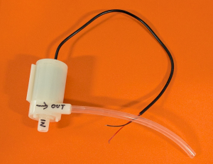
The submersible pump
Build a test circuit for the submersible pump using these parts:
- 12 V battery
- Alligator clips
- Push button switch, SPST
- Submersible pump
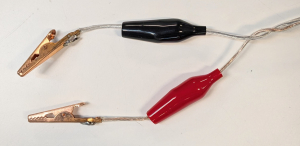
Keep the insulating covers on the alligator clips and make sure the bare wires do not touch (see detail in image).
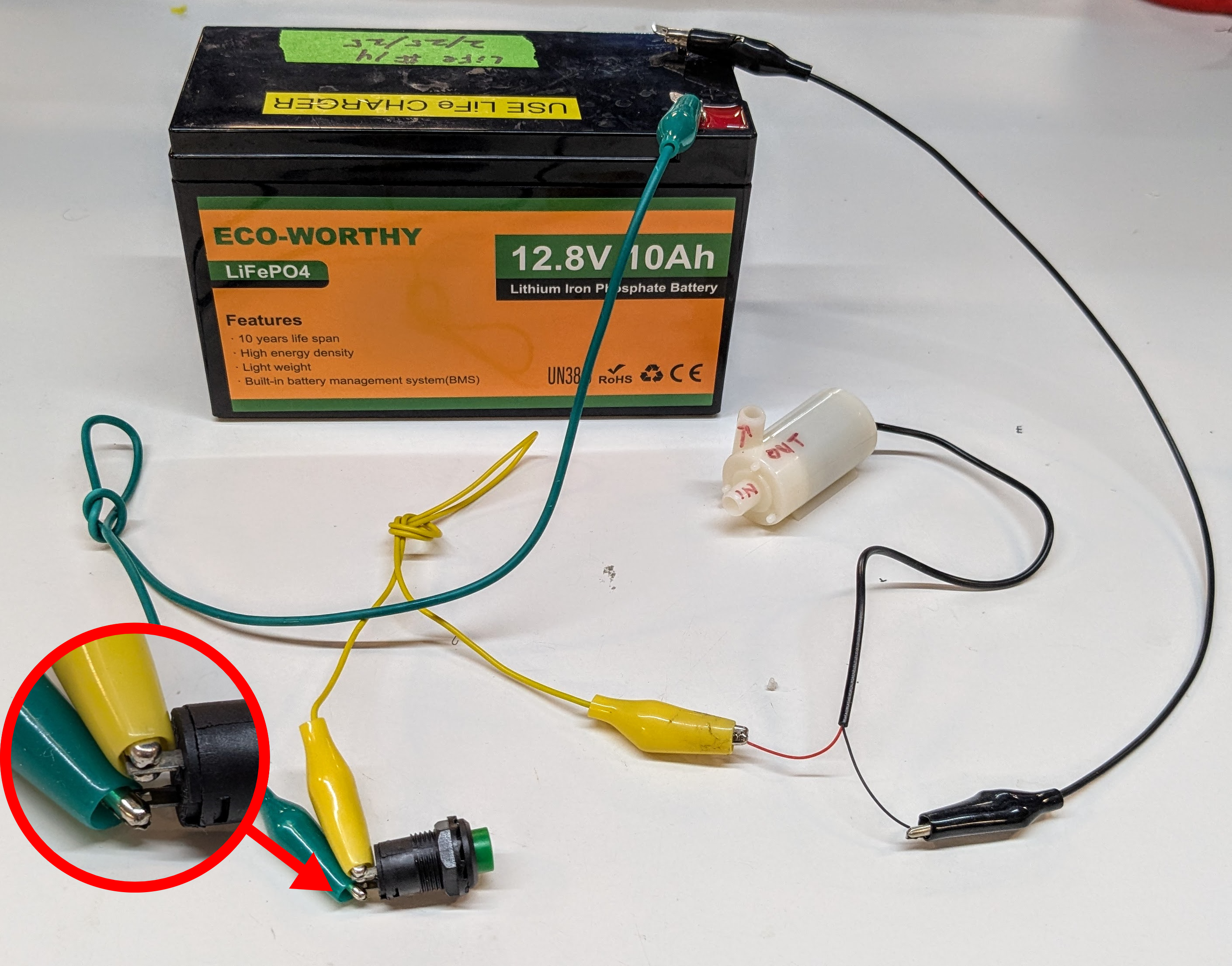
Test circuit: SPST switch, pump, battery in series
Put the pump in a sink or container full of water and turn it on and off with the push button switch.
If the pump does not expel water, reverse the polarity of the wires. Mark which terminal on the pump should connect to +12 V (red) and which connects to GND (black).
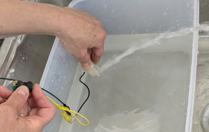
Pump operating in a tub of water.
Connect the pump to a gripper and see how the gripper works. The pump only closes the gripper; release the switch for the gripper to open.
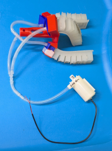
Pump connected to soft-robotic gripper
Step 2: Make a SeaPerch with a pump and gripper
Step 2: Make a SeaPerch with a pump and gripper
The powered gripper on the SeaPerch uses the extra wires in the ethernet cable, the brown and brown/white pair. It may be necessary to open the SeaPerch end of the cable to find the wires, then reseal the cable.
Connect the wires to the pump as follows:
- brown/white to the 12 V (+) side of the pump
- brown wire to the Ground (-) side of the pump
Brown and brown/white wires from cable
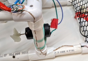
Build a gripper as detailed in the Soft-Robotic Grippers build guide, and mount it on a SeaPerch robot.
Connect the outlet of the pump to the inlet of the gripper with a piece of clear PVC tubing (1/8″ ID x 3/16” OD).
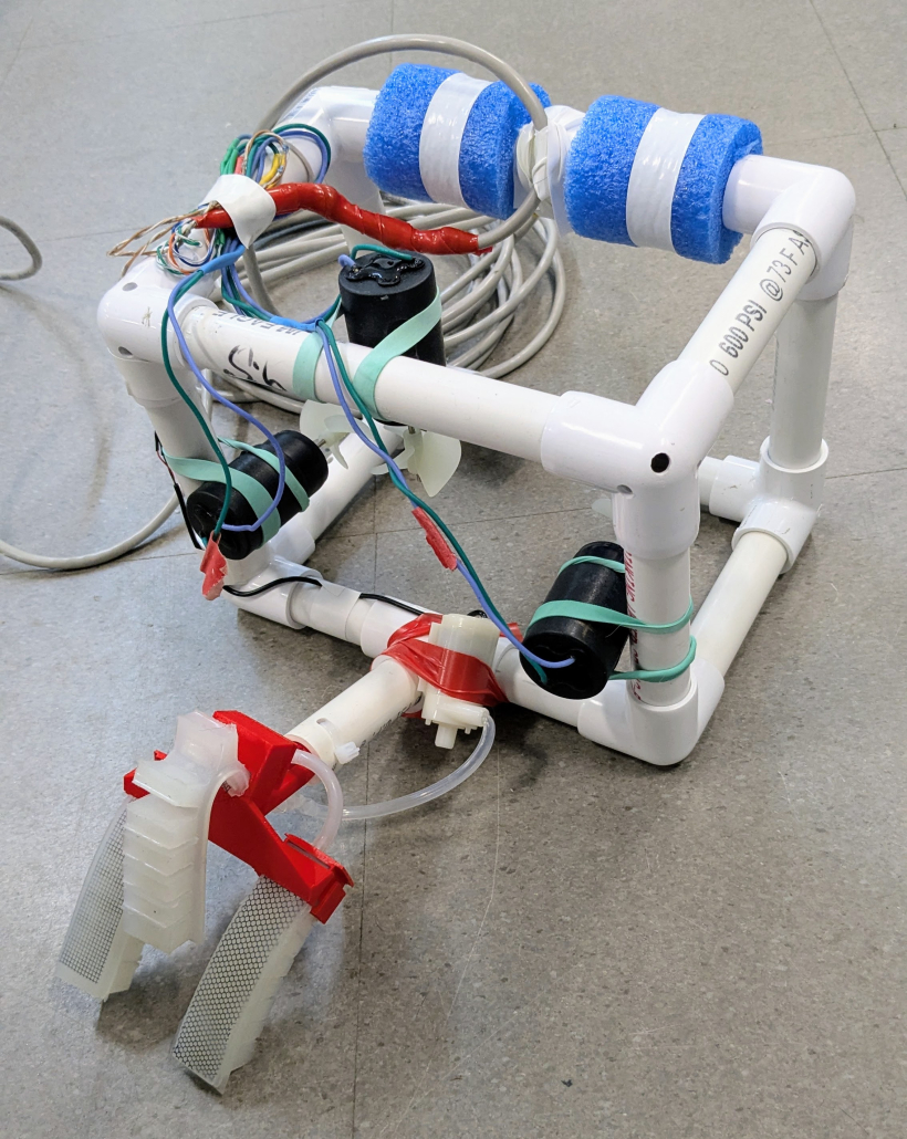
Gripper and pump mounted on SeaPerch
The SeaPerch and powered gripper are ready for the new controller.
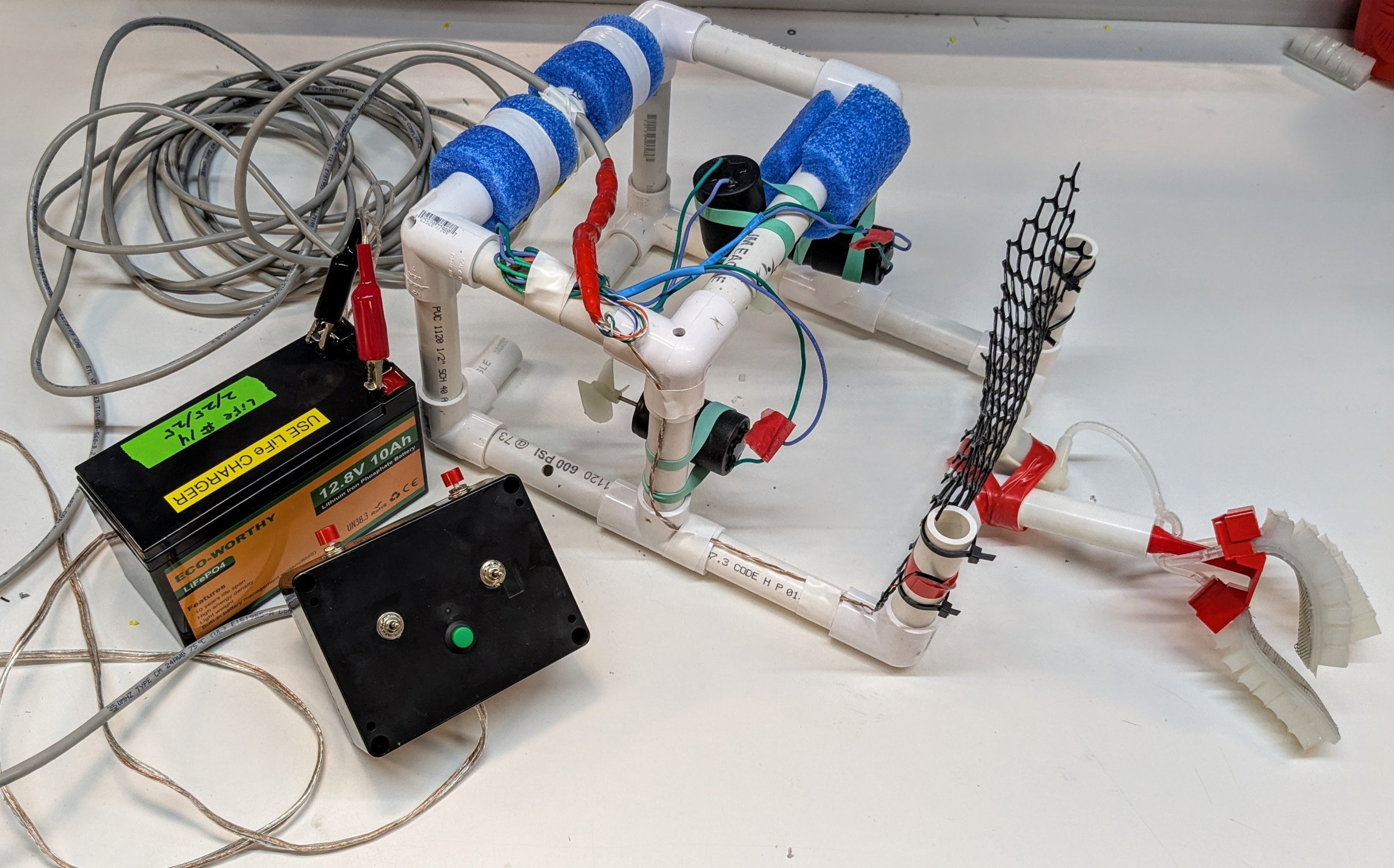
Full system: SeaPerch with powered gripper, controller, battery
Step 3: Collect tools and materials and practice fabrication skills
Step 3: Collect tools and materials and practice fabrication skills
- Collect materials and tools for electronics
- a. Wire strippers, wire cutters, needle nose pliers, hook up wire,
- b. Screwdrivers: medium Phillips head, small flat blade
- c. Soldering station (Iron, brass sponge, solder, tip cleaner)
- Practice stripping wire and turning the small screws on the ethernet connector
- Practice soldering
- a. Fasten the conductors to each other by twisting one around the other
- b. Heat the soldering iron, “tin” it with solder, and clean it off in the brass wool.
- c. Hold the soldering iron against the conductors
- d. Touch the solder to the soldering iron tip and the conductors and wait until it flows into the connection.
- Collect materials and tools for drilling
- a. Scrap wood or plastic
- b. Drill bits and step drill
- Practice marking and drilling holes in scrap material
- a. A set of step drills is highly recommended for drilling holes in thin wall material
- b. A marking punch is also a very useful tool
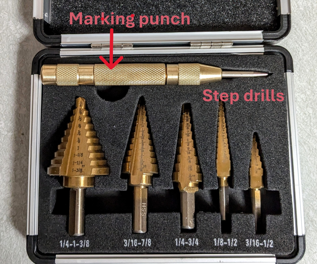
Punch and step drill set
Step 4: Choose a controller box style: adapt existing controller or build from scratch (DIY)
Step 4: Choose a controller box style: adapt existing controller or build from scratch (DIY)
To adapt a RoboNation controller, go to Step 13.
This requires good wiring and soldering skills.
Modified RoboNation controller
To build a completely new control box, continue on to Step 5.
This method takes longer but is a great way to learn wiring and fabrication skills.

Do-It-Yourself (DIY) controller
Step 5: Learn about the switches
Step 5: Learn about the switches
The switches to change direction on the left and right thruster motors are “Double Pole, Double Throw switches” (DPDT). They allow the polarity of the DC power to be reversed, changing the direction of the motor.
The push buttons for the up/down thruster are Single Pole, Double Throw switches (SPST). Wired together appropriately, they function as one DPDT switch.
For explanations of how each switch works in a circuit, see Science/Tech Note 5 – Circuits using DPDT and SPDT switches to reverse the spin direction of DC motors.
In addition to their electrical characteristics, the switches have important mechanical features that affect their function. Notice that the holes for the DPDT toggle switches and the SPDT push buttons each have a small hole near them. The small holes are for a special washer that the switches use to prevent them from rotating, ensuring the mechanical functions and the wiring are correct. View the images below and read on for more detail about how that works.
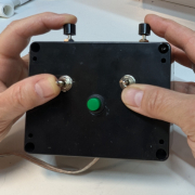
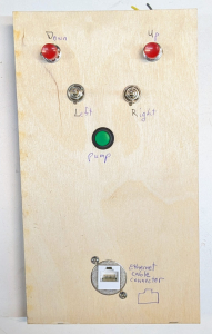
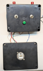
DIY controller box, front and top
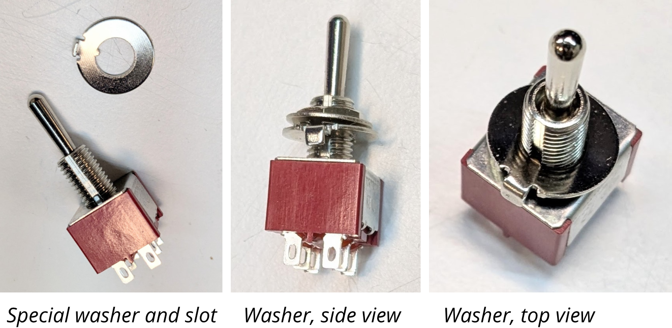
The switches have a groove on the threaded part and come with a special washer with an inner tab that fits the groove. The washer also has an outer tab that fits in the small hole preventing the switch from rotating once installed.
To install the switches properly, make sure the outer tab is facing away from the handle and fits into the small alignment hole. This ensures that the mechanical functions and the wiring are correct.
If the tabs do not fit well in the small holes, they can be bent in or out with needle-nose pliers.
Step 6: Make a build board for the controller box wiring
Step 6: Make a build board for the controller box wiring
Make a build board for the controller wiring to make the wiring and testing easier. (After testing on this board, the switches and connectors are removed from the board and installed in the electronics box.)
This board can easily be made on a laser cutter if one is available. An SVG file is included in the mechanical drawings folder.
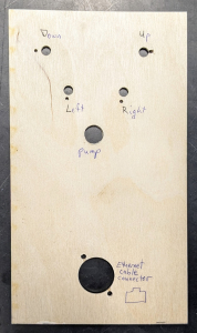
Build board, drilled and labeled
If making the board by hand, find the drawing in the mechanical drawings folder and print it out at full scale.
Cut a piece of ⅛” wood or acrylic roughly 5” x 8”.
Measure and mark the holes with a pencil, or print out the drawing and lay it over the board as a template. Use a marking punch (or tap a wood screw) to mark the exact locations with divots.
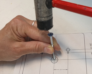
Marking holes with template and woodscrew
For the 1” hole, make sure to use a step drill and a drill press. If you do not have a drill press, practice drilling the hole on scrap material.
Drill the holes. This board is not part of the end product, so it is okay to drill extra holes if mistakes are made.
Mark “back” on the side of the board whether the small holes near the 1” hole are in the upper right and lower left. This side is where the solder and screw connections are made. On the front side, mark the functions of the buttons: down, up, left, right, and pump.
Step 7: Mark the controller box and drill the holes
Step 7: Mark the controller box and drill the holes
Find the appropriate drawings in the mechanical drawings folder and print them out at full scale.
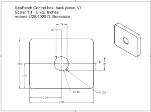
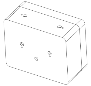
Controller box drawing, back piece
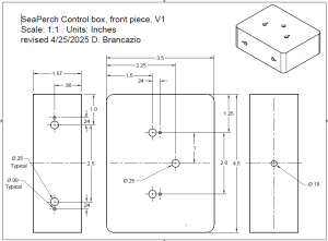
Controller box drawing, front piece
For both the front and back pieces of the controller box, measure and mark the holes with a pencil, or print out the drawing and lay it over the board as a template. Use a marking punch (or a wood screw) to mark the exact locations with divots.
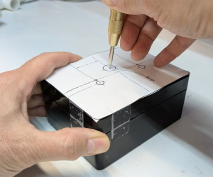
Marking holes with template and punch
For the 1” hole, make sure to use a step drill and a drill press. If you do not have a drill press, practice drilling the hole on scrap material.
Drill the holes and check that the switches fit in the holes.
Step 8: Make the power cable
Step 8: Make the power cable
Collect the 18 AWG 2-conductor cable and medium alligator clips (1 red and 1 black).
Cut a piece of cable about 8’ and strip the ends on both sides.
Install the alligator clips on one end, making sure the mechanical and electrical connections are strong.
Alligator clips connected to power cord
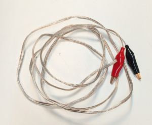
Power cable with alligator clips ends
Step 9: Install the switches and connector in the build board
Step 9: Install the switches and connector in the build board
Collect the switches and connectors for the build board.
Take each one apart and notice the order of the pieces. All of the components have lock washers. On the switches, the lock washers have “spikes” facing in. On the ethernet cable connector, the lock washers have a split.
Install the switches, making sure the outer tab on the special washer fits into the small alignment hole. If the tabs do not fit well in the small holes, they can be bent in or out with needle-nose pliers.
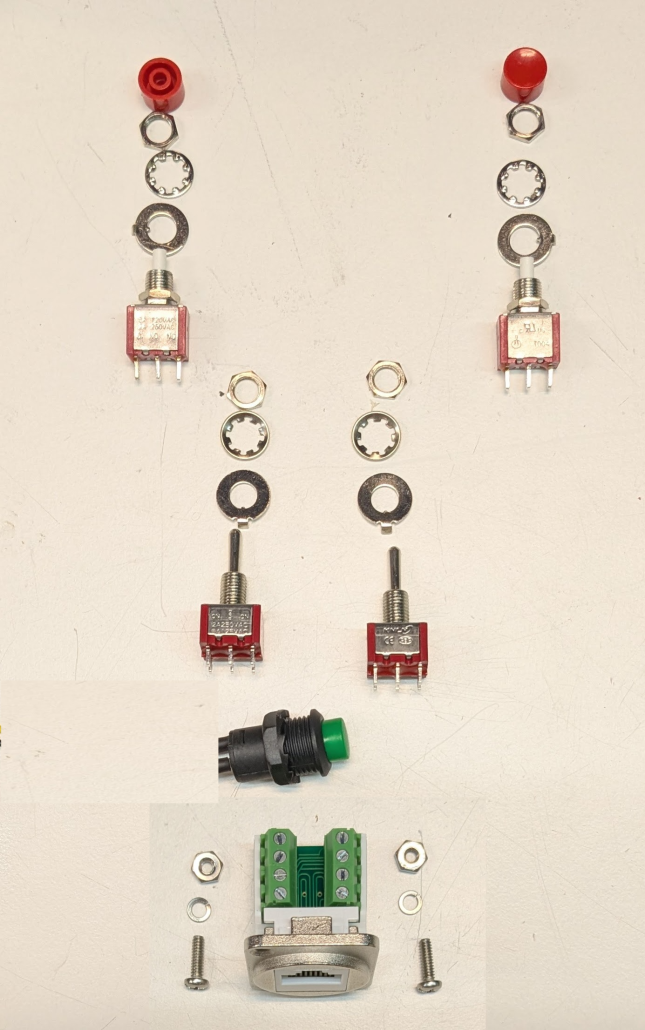
Electrical components, disassembled
Use pliers, such as the needle-nose pliers, to tighten the hex nuts and fasten the pieces on the board.
The completed build board should look similar to these images.
Build board and components, front
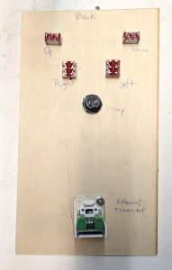
Build board and components, back
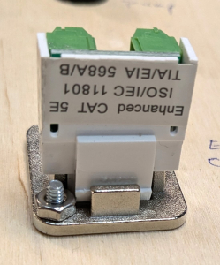
Screw on ethernet connector
Step 10: Wire the controller build board
Step 10: Wire the controller build board
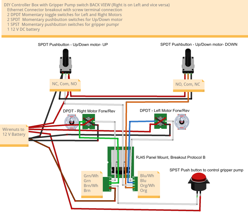
Wiring schematic for DIY controller box, as seen from the back of the build board
Find the wiring diagram in the mechanical drawings and electrical schematics folder and print it out. Notice that the wiring diagram is for the back of the build board, the side where the wiring is done.
Start by wiring the 12 V (red) and Ground (black) wires, which only go to the SPDT and DPDT switches. Do the “Xs” on the DPDT switches first.
Look for electrical “shorts” (wires touching other wires or tabs). If necessary, remove the wire, re-strip it so there is more insulation, and re-solder.
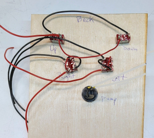
Build board with 12 V (red) and Ground (black) wires
Next, add the colored wires that go from the switches to the ethernet cable connector. Use wires a piece of ethernet cable if that is available. Otherwise use wire with colors that match the wiring diagram as much as possible.
Cut wires to about 9” long.
If using ethernet cable wire, leave the wire in twisted pairs, and only unravel the ends, except in the case of the brown and white pair. The brown wire has no connections at this point, and should be loose from the brown/white wire.
Solder to the switches first, being careful not to leave exposed wire that can touch other wires or tabs.
Wires soldered to all switches
Before making connections to the ethernet connector, trim all the wires so they are about the same length, and they all go past the connector by at least 3”.
Strip the ends about 3/16”, twist the strands of the wire, and bend the wire where the insulation ends. See image.
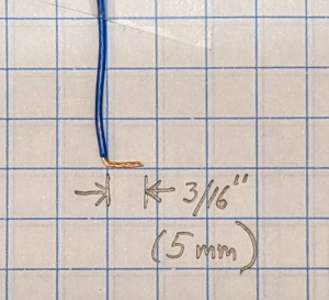
End of wire, stripped and bent
Loosen the screws on the ethernet connector and install the colored wires in the appropriate places. The color code is also shown on the side of the connector in “Style B”.
Make sure that there is no bare wire at the ethernet connections, and that the wires are held securely by the screws.
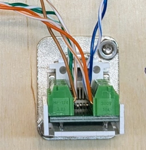
Wires installed in ethernet connector
The build board should have all connections complete except for the power cable (made in Step 8).
Collect the power cable and 2 medium size wire nuts.
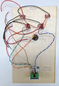
Build board with all wiring except for the power cable
Identify which wires on the power cable go to the red (12 V) and black (Ground) alligator clips. The wires go to the red and black wires on the build board respectively.
There will be 4 wires in each connection.
- 3 black wires and the brown wire
- 4 red wires
Strip each wire ½”
Put all the ends together and twist them only enough so they stay together. Insert the set of wires into the wire nut and twist it (clock wise) until it cannot twist anymore.
Check that the wires are securely fastened into the wire nut by pulling on each wire individually.
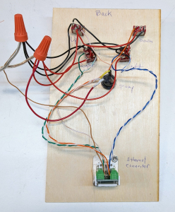
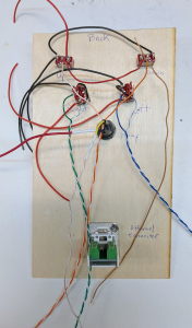
Build board with all wiring, back view
Step 11: Test the controller build board
Step 11: Test the controller build board
Collect the SeaPerch with powered gripper (from Step 2) and a 12 V battery.
The pump should not be run put of water, so be sure to have the SeaPerch in a bucket or tank of water when testing the pump.
Connect the SeaPerch and the 12 V battery to the build board and check that the controller works. Verify forward and reverse motion for all thruster motors. The pump only closes the gripper; release the switch for the gripper to open.
If operation is not as expected, look for disconnected wires or short circuits (conductors touching each other).
Step 12: Install the wiring in the controller box
Step 12: Install the wiring in the controller box
Disconnect the power cable from the build board by removing the wire nuts and untwisting the wires. This is necessary to install the power cable in the controller box.
Carefully remove the switches and the ethernet connector from the build board, making sure to keep all the hardware.
Install switches and ethernet connector in the electronics box.
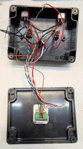
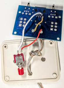
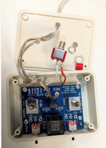
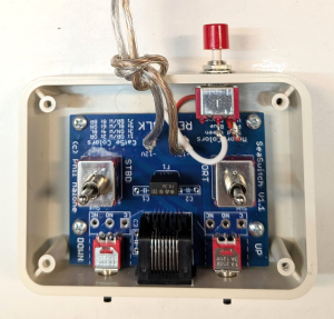
Inside of open controller box
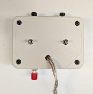
Outside of open controller box
Insert the power cable through the hole in the electronics box and tie a knot in it about 4” from the end. This creates a “strain relief” that keeps the cable from being pulled out of the box.
Reconnect the 12 V (red) wires and Ground (black) wires with the wire nuts.
Before closing the box, confirm the operation of the controller (connect to the battery and SeaPerch robot).

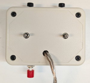
Knot in power cables that serves as a strain relief
Tuck all the wires in the box, seal the box, and confirm operation again.
Completed DIY controller box
Go to Step 16: Test and revise the gripper location
Step 13: Modify the RoboNation controller box
Step 13: Modify the RoboNation controller box
Steps 13, 14, and 15 contain instructions on adapting an existing SeaPerch controller to control a power gripper. While it is quicker than building a new box, it does require very good soldering skills.
Collect the materials and tools listed in early in the build guide.
Find the SPST pushbutton switch. (As shown in the image, the pushbutton switch can be made from a SPDT by cutting off the NC tab.)
Check that the pushbutton switch is small enough to fit in the controller box. The switch body should extend no more than 1” into the box, and be nor greater than ⅜” deep or wide.
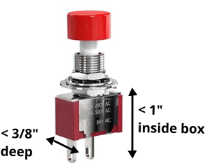
Size limits for SPST pushbutton switch
Disassemble a controller and remove the pc board.
The power cord can stay as it was.
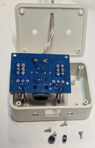
Disassembled RoboNation controller
Measure the diameter of the switch body (likely to be ¼”) and drill a hole in the box as shown.
- 1” from the side
- ⅜” from the open face
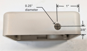
Location and size of hole for pushbutton
Step 14: Wire the switch to the circuit board
Step 14: Wire the switch to the circuit board
Identify the following solder tabs on the back of the board:
- solder tabs on the ethernet connector for the the brown and brown/white wires
- the solder tabs for the +12 V and GND power cable
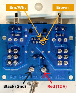
Locations of electrical connection points for pump
Cut 6” pieces of 24 AWG hook-up wire in red, white, and brown (or keep note of the colors).
Prepare the brown and white wires, strip the end about 3/16”, twist the stands together tightly and make a small loop of wire. Place the loop around the solder tabs of the ethernet connector and solder the loop on. Check to make sure no wires are touching any other wires.
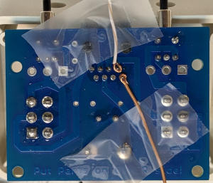
Brown and white wires on ethernet connector tabs
For the red and brown wires on the power connector, strip the end about 1/4”, twist the stands together tightly and make a small loop of wire. Place the loop around the solder tab and solder the loop on.
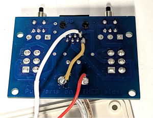
Brown and red wires on the 12 V and Ground tabs
Cut the red and white wires to reach the switch. Leave enough room to manipulate the switch after the circuit board has been re-installed.
Solder the wire to the switch (the tabs do not matter).
Brown and red wires on the 12 V and Ground tabs
Step 15: Test the new wiring and install the switch in the box
Step 15: Test the new wiring and install the switch in the box
Connect the box to the modified SeaPerch and check the operation of the pump. Remember that the pump should not operate out of water. If the pump is not submerged in water, only run it for a split second.
Once the wiring is verified, re-install the circuit board in the box.
Disassemble the switch (remove the cap, the lock washer and the hex nut).
Board installed in box, switch disassembled
Install the switch in the box. Make sure to include the lock washer. Use pliers to tighten the nut.
Check that the switch wires are not touching watch other.
Switch installed in box
Screw the front plate onto the box.
Check the operation of the pump again.
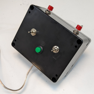
Modified RoboNation controller box
Step 16: Test and revise the gripper location
Step 16: Test and revise the gripper location
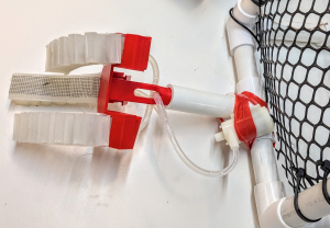
Find a good place to install the gripper. Check the buoyancy and balance of the SeaPerch as the pump will be adding weight.
Install the gripper as per the soft-robotic gripper build guide. Run a piece of tubing to the pump and attach the pump with stretchy tape, such as electrical tape or silicone tape. Make sure there are no kinks in the tubing that could block water flow.
Purge the system of air by disconnecting the pump from the gripper and running it under water. Squeeze the grippers underwater to remove the air from them.
Test and revise until the performance is satisfactory.

Who can build it: The activities here are recommended for middle to high school students.
Knowledge and skills developed in this project:
- Hand fabrication including measuring, marking, drilling and assembly
- Electronics fabrication including wiring and soldering
Safety: The fabrication activities include wiring, soldering, drilling, and hand assembly. Tool and shop safety measures include following directions on any tools and materials, wearing personal protective equipment (PPE) such as safety goggles, maintaining an orderly working space, and working with adult supervision.
Cost estimate (lower number assumes basic lab materials are available for use):
- For 3 gripper pumps and adapted RoboNation controllers: ~$20 – $150
- For 3 gripper pumps and 3 DIY robust controllers: ~$70 – $160
