SEAPERCH II MODULE 3:
Soft Robotics Grippers
Make your own simple and inexpensive soft-robotic grippers that can pick up and put down objects. Push down on a syringe to curl the grippers and pull back on the syringe to release the grippers.
The gripper is completely DIY, from the 3D printed molds and gripper mounts to the cast silicone grippers themselves. The actuation system requires only common plastic syringes, tubing, and fittings. The grippers help an underwater robot, such as the SeaPerch, transport items from one place to another by gently grabbing and releasing them. The grippers and the hydraulic actuation system are filled with water, so the buoyancy of the underwater robot is not affected. Grippers can be built for a variety of needs by choosing the number of fingered, the orientation of the fingers and the lengths of the fingers.
How it works
The “gripper” is an inexpensive and simple attachment that allows the SeaPerch to pick up and put down objects. The silicon gripper has a knuckled design and is attached by thin plastic tubing to a syringe above the water. When the syringe is pushed, the knuckles of the grippers are inflated and the gripper curls up to grab the desired object. To release the object, the syringe is retracted and the knuckles are deflated. To create a gripper that functions similar to a human hand, mount several fingers on a holder and use a larger syringe to actuate them all at once.
This guide outlines the steps for making a gripper system than can be easily mounted on the PVC frame of the SeaPerch.
Knowledge and skills needed:
Basic hand fabrication
Measuring and handling chemicals
Safety: Practice chemical safety and follow directions on any materials used in this module, (e.g., work in a properly ventilated area and wearing safety glasses, and vinyl gloves).
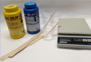
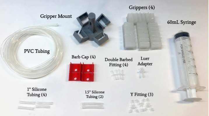
Project tools and materials
Project Tools and Materials:
These materials can be used to make dozens of soft-robotic grippers.
| Item | Source | Cost each | Qty |
| Ecoflex 00-30 Silicone (Parts A and B) 1 pound each | Amazon.com: Ecoflex 00-30 – Super-Soft, Addition Cure Silicone Rubber – Pint Unit | $40 | 1 |
| Jumbo Wooden Craft Sticks 200/pk | https://www.amazon.com/gp/product/B0721TJS5X/ | $17 | 1 |
| Disposable mixing cups, with wood mixing sticks, 8oz, pack of 100 | https://www.amazon.com/gp/product/B09DC81CPC | $17 | 1 |
| Mixing Cups, Graduated, 1 ounce, 400/pk | https://www.amazon.com/gp/product/B07SXBN17D/ | $12 | 1 |
| Vinyl gloves, disposable, powder-free, latex-free, Medium 100/box | https://www.amazon.com/gp/product/B09KM5LWL1/ | $6 | 2 |
| 3D printed molds | Gripper molds and mounts | ||
| Window screen mesh, plastic | https://www.amazon.com/dp/B083NPV66H/ | $10 | 1 |
| Electrical tape, 3/4″ x 50′ roll, 3 rolls/pack | https://www.amazon.com/Duck-299004-Professional-Electrical-0-75-Inch/dp/B002VKT22O/ | $8 | 1 |
| 3” masking tape (2” is ok also) | https://www.amazon.com/GTSE-Masking-Multi-Surface-Adhesive-Painting/dp/B088WW2LK7/ | $6 | 1 |
| 60ml Syringes, plastic, Luer Lock, 10 pack | https://www.amazon.com/Individually-Scientific-Measuring-Dispensing-Applicator/dp/B0BGHT9NNJ/ | $13 | 1 |
| 20ml Syringes, plastic, Luer Lock, 10 pack | https://www.amazon.com/Individually-Scientific-Measuring-Dispensing-Applicator/dp/B0B7F226M9/ | $10 | 1 |
| Clear PVC tubing, 1/8″ ID x 3/16″ OD, 33’/roll | https://www.amazon.com/gp/product/B09DYWL124/ | $10 | 2 |
| Silicone tubing, 1/8″ ID x 3/16″ OD, 10’/roll | https://www.amazon.com/Metaland-Silicone-Tubing-Brewing-Winemaking/dp/B08XM1V475/ | $9 | 1 |
| 2-way Hose Barb Fitting, 1/8″ x 1/8″, 15/pack | https://www.amazon.com/gp/product/B095YSPRPL/ | $10 | 2 |
| Female Luer lock to barb fitting, 1/8″, 30 pcs/pack | https://www.amazon.com/gp/product/B0BMFJSJP1/ | $10 | 1 |
General tools and materials
General Tools and Materials:
- 3D printer and filament
- Scissors
- Vinyl gloves
- Paper towels
- Small drill bit/push pin/toothpick
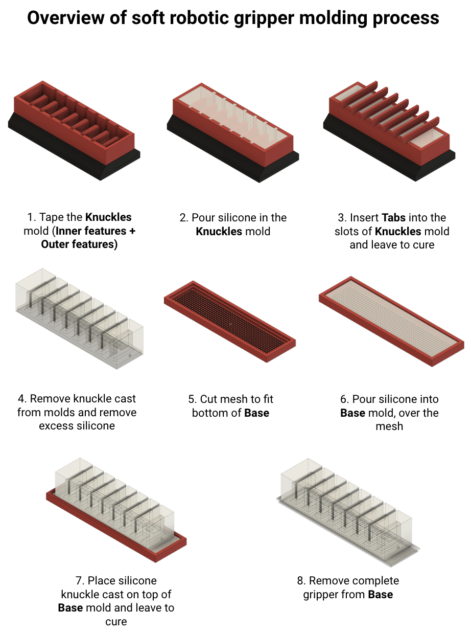
Overview of sensor molding process
Part 1 - Print molds and the mount
Part 1 – Print molds and the mount
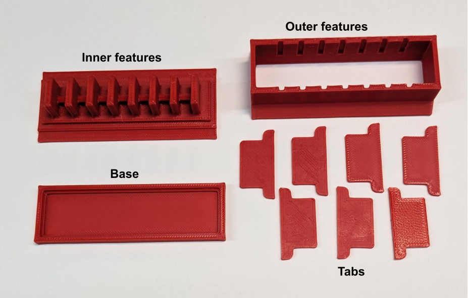
Step 1.1: Print the molds (Inner features, Outer features, Tabs and Base)
Make the ten mold pieces on the 3D printer: the Inner features, the Outer features, the Base, and seven Tabs. Check that the seven Tabs can fit in the slots of the Outer features mold. Trim any pieces that interfere with a good fit. Check that the Outer features mold fits on top of the Inner features mold. Trim any pieces that interfere with a good fit. Set aside the Base for now.
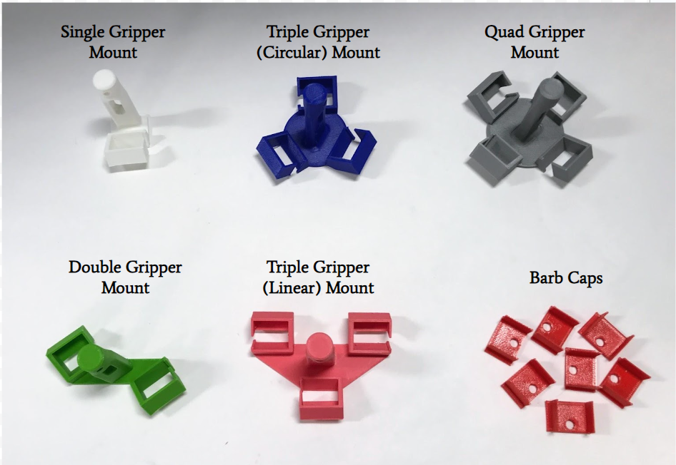
Step 1.2: Print the mount and barb caps
Print your desired mount and print a barb cap for each gripper you plan to make.
Part 2 - Cast the grippers
Part 2 – Cast the grippers
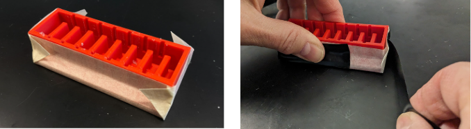
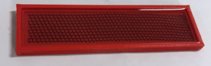
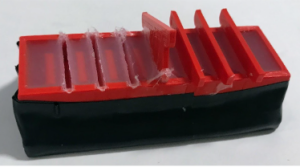
Step 2.1: Prepare the Knuckles mold
Clean the outside of the Outer features mold and the bottom of the Inner features mold with alcohol wipes.
Cut one piece of 3’’ wide, 5.25’’ long craft tape and one 12” piece of electrical tape.
Stack the Inner features and Outer features together and put them on the craft tape.
Seal the seam between the Inner features and Outer features with tapes as follows:
First seal the length of the molds by folding the long edges over. Fold and pinch the corners.
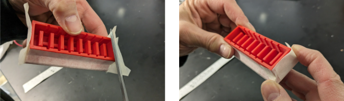
Next, use the scissor to cut the tape edges flat. Seal the width of the molds by folding the short edges over. Fold and pinch the corners.
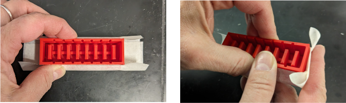
The tape should all be folded neatly around the mold, be below the top of the mold, and sit flat on the table.
Cut a piece of electrical tape about 12” long. Wrap it around the entire perimeter of the mold, aligning to the bottom edge, and making sure the mold still sits flat on the table.
Step 2.2: Prepare the Base mold
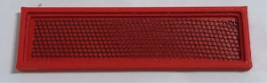
Cut out a strip of plastic mesh (as used in screen windows) using the Base mold as a guide. Measure or trace the inside of the Base mold and mark it on the mesh. Cut the mesh and check to see if it fits in the Base mold without going up the sides. Trim as needed.
Step 2.3: Measure and mix Ecoflex 00-30 silicone rubber
Ecoflex 00-30 has two parts: part A and part B. When these two parts are combined, they cure to form a solid, soft rubber-like material. The ratio of A:B is 1:1, and it can be measured by weight or volume. In either case, use a disposable plastic cup and wear vinyl gloves to protect skin.
Before you mix A and B together, stir parts A and B individually and thoroughly. Use a long sturdy mixing stick that reaches the bottom of the jars so you can scrape the bottom and the sides. The first time you mix the compounds, it could take 10 minutes of rigorous mixing for each jar.
Next you will measure and mix parts A and B in the quantity you need. The chart below shows the amount needed for each type of gripper and base.
Volume of silicone
| Knuckles (ml or g) | Base
(ml or g) |
|
| Short (6 knuckle) | 14 | 2.5 |
| Long (8 knuckle) | 18 | 3 |
| X Long (10 knuckle) | 23 | 4 |
Once mixed you only have 30 minutes before the silicone starts to set. (This is called the “pot life” of the compound). To make one gripper, use one of the methods below. To make multiple grippers, multiply the amount listed by the number of grippers desired.
- Scale method: Place the plastic cup on the scale and zero the scale. Pour 15 g of part A into the cup, then pour 15 g of part B into the cup. The scale should read 30 g.
- Volume method: Pour part A into the cup up to the 15 ml line, then pour part B into the cup up to the 30 ml line.
Mix slowly and thoroughly for 30 – 60 seconds using a clean wood stick, scraping the sides and bottom of the cup. Do not stir quickly as it causes air bubbles to form. Refer to Science/Tech Notes or EcoFlex instructions for more details.
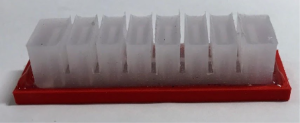
Step 2.4: Pour silicone into the molds
Slowly pour silicone into the Knuckles mold (the Outer Features mold and the Inner Features mold, sealed together with tape).
Fill the mold until it reaches slightly below the top.
Place all Tabs into the slots of the Knuckles mold. Top off the mold with the Ecoflex 00-30 mix if necessary.
For the Base mold, pour a strip of the silicone down the middle of the mold over the mesh. Do not try to pour to a level as the silicone is too viscous for that. Using a clean wood stick, push the silicone around until an even layer is reached all around. The goal is to have it filled partially, just to the top of the first wall. However, it is okay to be slightly over.
Step 2.5: Wait for silicone to cure
Let all molds sit for 4 hours in a well-ventilated space while the silicone cures.
Step 2.6: Remove knuckle cast from the molds and remove excess silicone
Remove the Tabs by pushing up on the arms of the Tabs.
Remove all the tape.
Pry the two pieces of the mold apart by inserting a flat blade screwdriver in the gap and twisting it. Do this in several places around the mold until you can pull them apart by hand.
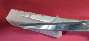
Gently remove the silicone from the Knuckles mold.
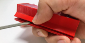
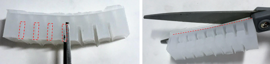
Carefully remove silicone between the knuckles and along the bottom edge of the gripper. Scissors work well for this.
Remove any other excess silicone with scissors or pliers.
Step 2.7: Measure and mix Ecoflex 00-30 silicone rubber
Prepare a small amount of silicone to bond the upper part of the silicone to the base. Refer to Step 2.3, for the amounts (Base), and for the measuring and mixing procedures.
Step 2.8: Pour silicone into Base mold over the mesh
For the Base mold, pour a strip of the silicone down the middle of the mold over the mesh. Do not try to pour to a level as the silicone is too viscous for that. Using a clean wood stick, push the silicone around until an even layer is reached all around. The goal is to have it filled up to the top of the first wall, but it is okay to be slightly over.
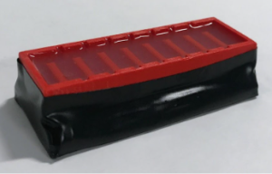
Step 2.9: Place silicone knuckles on top of Base mold and leave to cure
Gently place the silicone knuckles on top of the Base mold. Do NOT press down as this may push the silicone into the air chambers and block them.
Let the mold sit for 4 hours in a well-ventilated space while the silicone cures.
Part 3 - Test single gripper
Part 3 – Test single gripper
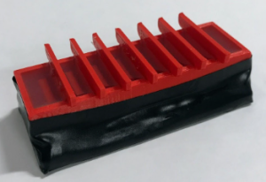
Step 3.1: Extract gripper(s)
Gently remove the gripper from the Base mold.
Trim the base silicone so it does not protrude from the side of the gripper.
Step 3.2: Use drill bit/toothpick to create a hole in gripper
Find the divot molded into 1 side of the gripper. If you can not find the divot, it is possible that it was covered with silicone. If this happens, mark a spot close to the bottom and in the center where the air channel is.
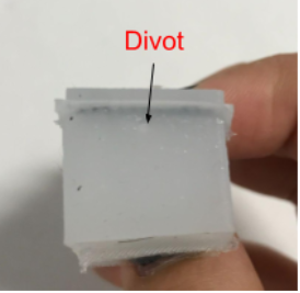
Using a small drill bit (~ 1/16” or 1.5 mm) or toothpick, poke a hole through the silicone where the divot is. Be careful not to poke a hole through the sides of the gripper.
If the air chamber is not blocked, the drill or toothpick should slide in easily after it breaks through the wall. This hole will stretch to go around the barb fitting.
Step 3.3: Assemble tubing, syringe, and gripper
Gather these materials and assemble a test rig for the gripper:
- PVC plastic tubing, ⅛” ID, 1 – 2’ length
- ⅛” 2-way barb fitting
- Luer – ⅛” barb connector
- 20 ml syringe with Luer connector
Step 3.4: Fill the test rig and the gripper with water
Fill the syringe and long piece of PVC tubing with water by alternately pulling in water and pushing out air. Keep the barb fitting end of the PVC tubing up higher than the syringe to purge the air.
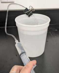
Hold the gripper under water and squeeze them several times to squeeze the air out and let water in.
Step 3.5: Test gripper(s)
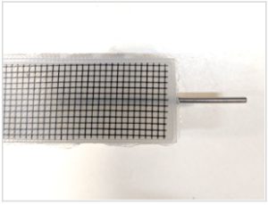
Insert the barb fitting into the hole on the gripper. This can be tricky – try several angles.
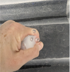
Test the gripper by pushing and pulling back on the syringe. Pushing the syringe down should cause the knuckles to inflate evenly and the gripper to curl. Pulling back should relax the gripper.
If the knuckles are not uniform there was likely a problem in the mold itself or in the casting.
Water coming out anywhere indicates a leak – look for problems in your fabrication.
Try to get the air out of the gripper by keeping it lower than the syringe and squeezing it when you deflate it.
Part 4 - Assemble grippers to mounts
Part 4 – Assemble grippers to mounts
Assembly instructions for each Gripper follow in this order:
- Step 4A: Single gripper assembly
- Step 4B: Double Gripper assembly
- Step 4C: Triple Gripper (linear) assembly
- Step 4D: Triple Gripper (circular) assembly
- Step 4E: Quad Gripper assembly
General summary for all gripper types. Detailed instructions follow.
Gripper assembly process:
- Gather all materials
- Insert barbs into appropriate silicone tubing
- Slide cap onto tubing
- Squeeze grippers underwater to remove as much air as possible
- Attach grippers while still underwater (make sure tubing is underwater)
- Slide grippers into mount
- Slide cap into gripper mount
- Attach rest of silicone tubing/fittings underwater, leave underwater
- Fill syringe with water
- Attach syringe to PVC tubing and purge air from line
- Attach PVC tubing to assembly while underwater
Step 4A: Single gripper assembly
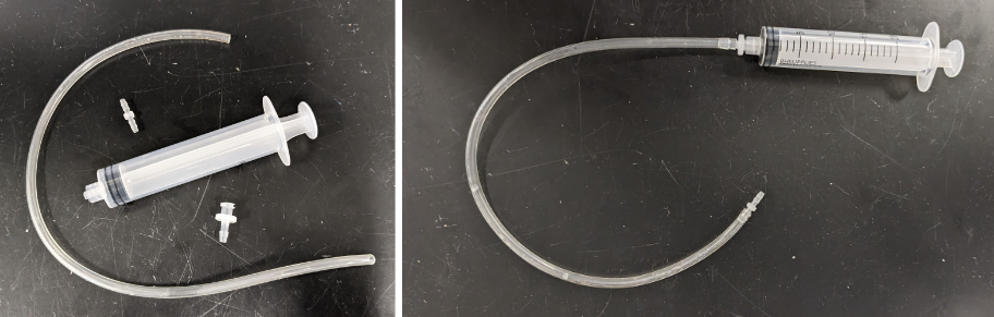
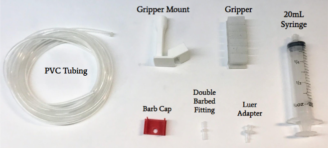
Step 4A.1: Collect materials for Single Gripper
Collect these materials:
- PVC tubing
- 1 double-barb fitting
- 20mL syringe
- Luer adapter
- Gripper
- Single gripper mount
Cut the PVC tubing as long as desired.
Step 4A.2: Assemble tubing and fittings with Single Gripper mount
- Insert the tubing through the mount and the Barb Cap, then insert the barb connector.
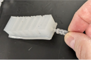
- Insert the barb into the gripper.

- Slide the gripper into the mount through the open end.
- Fit the gripper end into the mount.
- Slide the Barb Cap down the tubing and gently push it into the mount around the rubber of the gripper. The barb fitting should push through the Barb Cap.

Step 4B: Double gripper assembly
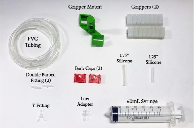
Step 4B.1: Collect materials for Double Gripper
Collect these materials:
- PVC tubing
- Silicone tubing
- 2 double-barb fittings
- 1 3-way Y barb fitting
- 60mL syringe
- Luer adapter
- 2 Grippers
- Double gripper mount
Cut the PVC tubing as desired.
Cut (1) 1.25’’ piece and (1) 1.75’’ piece of silicone tubing.
Step 4B.2: Assemble tubing and fittings with Single Gripper mount
Follow the steps as shown for the single gripper in Step 4A.2 or for the triple gripper in Step 4C.2.
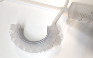
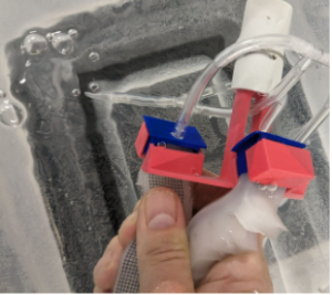
The completed double gripper assembly should look like the images shown here.

Step 4C: Triple gripper (linear) assembly
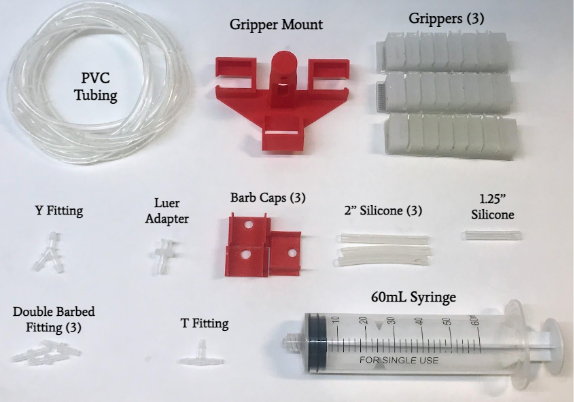
Step 4C.1: Collect materials for Triple Gripper (linear)
Collect these materials:
- PVC tubing
- Silicone tubing
- 3 double-barb fittings
- 1 3-way Y barb fitting
- 1 3-way T barb fitting
- 60mL syringe
- Luer adapter
- 3 Grippers
- Triple gripper mount (linear)
Cut (1) 1.25’’ piece and (3) 2’’ pieces of silicone tubing.
Cut the PVC tubing as desired.
Step 4C.2: Assemble tubing and fittings with Triple Gripper (linear) mount
- Insert the tubing through the mount and the Barb Cap, then insert the barb connectors.
- Insert the barbs into the gripper.

- Slide the grippers into the mount through the open end.
- Fit the gripper ends into the mount.

- Slide the Barb Cap down the tubing and gently push it into the mount around the rubber of the gripper. The barb fitting should push through the Barb Cap.
- Completed gripper

The completed triple gripper (linear) assembly should look like the images shown here.

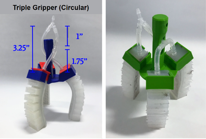
Step 4D: Triple gripper (circular) assembly
Step 4D.1: Collect materials for Triple Gripper (circular)
Collect these materials:
- PVC tubing
- Silicone tubing
- 3 double-barb fittings
- 1 3-way Y barb fitting
- 1 3-way T barb fitting
- 60mL syringe
- Luer adapter
- 3 Grippers
- Triple gripper mount (linear)
Cut (1) 1’’ piece, (2) 1.75’’ pieces, and (1) 3.25’’ piece of silicone tubing.
Cut the PVC tubing as desired.

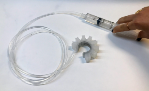
Step 4D.2: Assemble tubing and fittings with Triple Gripper (circular) mount
Follow the steps as shown for the triple gripper in Step 4C.2.
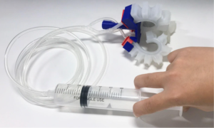
The completed triple gripper (circular) assembly should look like the images shown here.
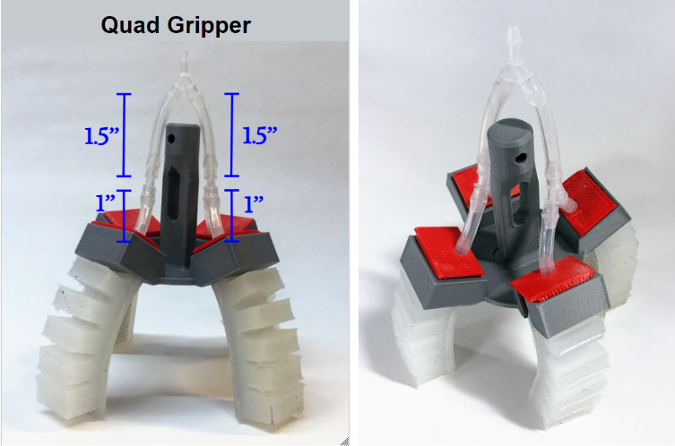
Step 4E: Quad gripper assembly
Step 4E.1: Collect materials for Quad Gripper
Collect these materials:
- PVC tubing
- Silicone tubing
- 4 double-barb fittings
- 3 3-way Y barb fitting
- 1 3-way T barb fitting
- 60mL syringe
- Luer adapter
- 4 Grippers
- Quad gripper mount
Cut (4) 1’’ pieces, and (2) 1.5’’ pieces of silicone tubing.
Cut the PVC tubing as desired.
Step 4E.2: Assemble tubing and fittings with Quad Gripper mount
Follow the steps as shown for the triple gripper in Step 4C.2.
The completed quad gripper assembly should look like the images shown here.
Part 5 - Test the gripper system in water
Part 5: Test the gripper system in water
Step 5.1: Fill the system with water
Before attaching the gripper to a SeaPerch robot, prime it with water and test it.
Fill the syringe and long piece of PVC tubing with water by alternately pulling in water and pushing out air.
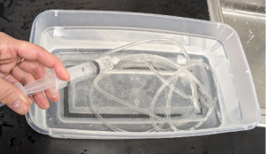
Hold the grippers under water and squeeze them several times to squeeze the air out and let water in.
Step 5.2: Test the gripper assembly
Test the gripper by pushing and pulling back on the syringe.
Pushing the syringe down should cause all the grippers to curl and pulling back should relax the grippers.
Make sure that the grippers do not have any holes and are not leaking water.
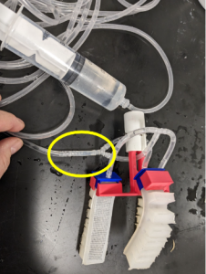
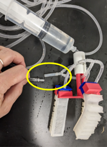
Step 5.3: Optional – Add small silicone tubing section to make it easier to remove air from the system
It is much easier to remove the barb fitting from the silicone tubing than from the PVC tubing. Add a small piece of silicone tubing between the gripper connection and the long PVC tubing.
Open this connection when purging air from the system.
Part 6 - Mount gripper on SeaPerch
Part 6 – Mount gripper on SeaPerch
Step 6.1: Connect grippers to SeaPerch with PVC pipe adapter
The gripper assembly will be attached to the SeaPerch robot with a short piece of PVC pipe. The pipe fits around the gripper mount, and into a PVC fitting.
Obtain a short piece of PVC pipe and drill a hole (~3/16” or 0.5cm diameter) through it, near one end (~½” or 6 mm) away.

Slide the PVC pipe over the gripper mount and fasten with a piece of wire or a zip tie.

Attach the small piece of pipe to the SeaPerch by pushing it into a PVC fitting. The gripper can be rotated as needed by rotating the PVC pipe in the fitting.

Step 6.2: Tape or zip tie tubing to SeaPerch frame
Tape or zip tie the PVC plastic tubing along the frame of the SeaPerch to prevent any tangling. Make sure that the tubing is not constricted and is out of the way of the motor propellers.

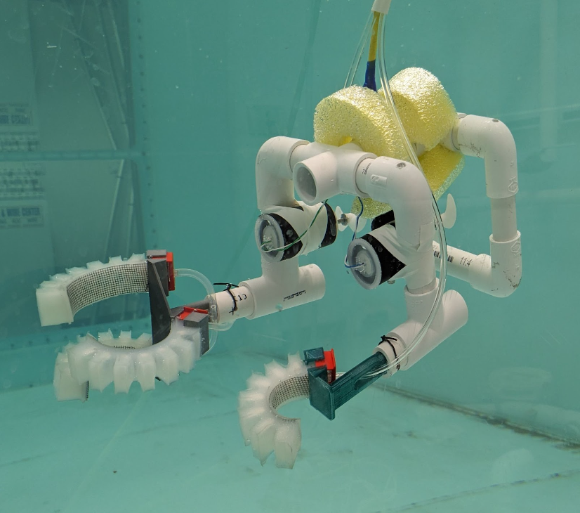
Step 6.3: Test grippers on SeaPerch underwater
Put the SeaPerch underwater and test the grippers with the whole system.
Video: Gripper demo 12-20-23

Knowledge and skills needed:
Basic hand fabrication
Measuring and handling chemicals
Safety: Practice chemical safety and follow directions on any materials used in this module, (e.g., work in a properly ventilated area and wearing safety glasses, and vinyl gloves).
Cost for a group of 10 – 20: ~$200 (or less if repurposing other materials)
