SEAPERCH II SCIENCE/TECH NOTES
Each SeaPerch II module links to additional Science/Tech Notes by topic, which can be found all together on this page.
Science/Tech Note 1: Making rubber with two-part silicone
Making rubber with two-part silicone
Soft, strong, stretchable silicone rubber can be made easily and quickly with products that are readily available and reasonably priced. The properties of this material make it a good choice for soft robotics and for waterproofing electronics. The silicone used for the examples in this book is addition cure silicone rubber called Ecoflex™ 00-30 and is made by Smooth-On, Inc.
The silicone rubber kit consists of 2 liquid materials which are portioned out 1:1 by weight or volume, mixed for 3 minutes, then poured into a prepared mold. At room temperature, the pot life (workable time) is 45 minutes, and the cure time is 4 hours. For safety, users should wear safety glasses and vinyl gloves (latex inhibits the cure), work in a clean, well-ventilated area, and line the surface with a disposable material.
Due to the strong, stretchable nature of the material, it is easy to remove it from a mold, though there is a mold release agent that can be used.
https://www.smooth-on.com/products/ecoflex-00-30/
Without a scale, measure the silicone by volume using a graduated mixing cup. For small amounts, use a small cup, or measure amounts in with plastic spoons, being careful to level the top before adding to the mixing cup.
Science/Tech Note 2: How the silicone stretch sensor works in a circuit
How the silicone stretch sensor works in a circuit
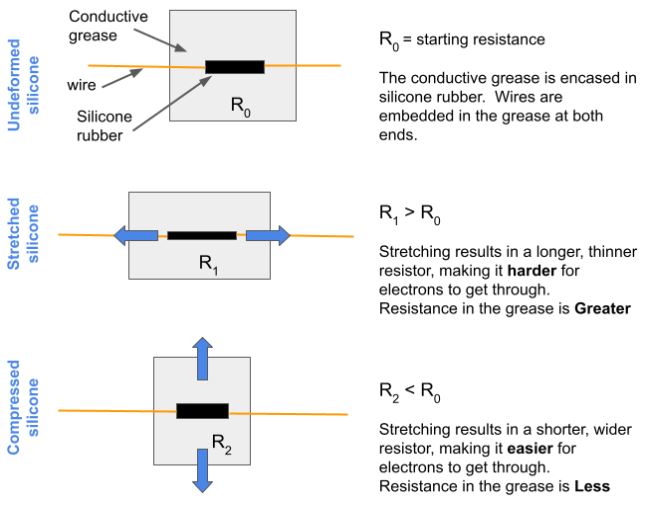
Electrically conductive grease is used on electrical connectors and switches that are in rough environments. It ensures good electrical contact while protecting against corrosion and moisture.
Like any electrical conductor, this grease has a small internal resistance, but the resistance is negligible when the grease is used as a very thin coating.
In this application, however, the grease is used to create a long conductive path in a base of silicone rubber, and its resistance is important. When the silicone rubber is stretched, the “grease resistor” changes shape and its resistance changes. Starting with the same material, a longer thinner resistor will have greater resistance to the flow of electrons, and an a shorter wider resistor will have lower resistance.
Therefore, a force on the silicone rubber base that deforms the grease resistor will result in a change in resistance, and that can be detected with a simple circuit.
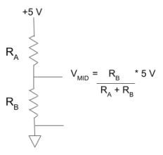 To detect the change in resistance, the grease resistor is used in a voltage divider circuit along with a resistor of similar size. The supply voltage in theses examples is +5 V. The 2 resistors are in series and therefore have the same current through them. The voltage drop across each resistor can then be determined using Ohms Law: V = IR. In a voltage divider circuit, the resistors split the total supply voltage in proportion to their size – the larger resistor has a larger voltage drop across it than the smaller resistor.
Here is the schematic and equation for a voltage divider circuit.
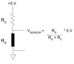
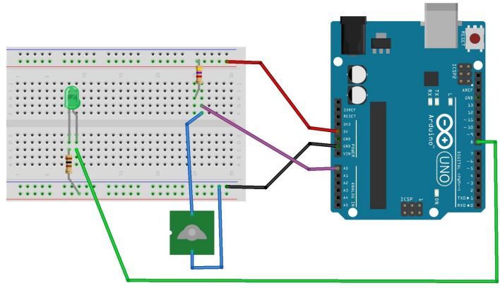
In the case of the silicone sensor, the grease resistor in the is placed on the lower part of the circuit so that the Arduino microcontroller can read the voltage drop across it relative to Ground, as shown in the circuit. The voltage drop across the sensor (VSENSOR) increases when the resistance of the conductive grease increases, and vice versa, indicating the type of distortion in the silicone rubber. The VSENSOR wire is connected to an analog input on the Arduino microcontroller and the voltage is converted to an integer between 0 and 1023.
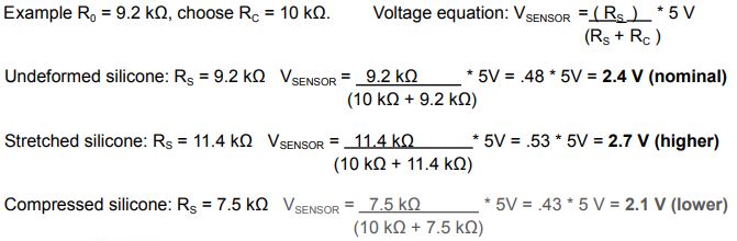
 To determine a value for Rc, use a multimeter to measure the resistance of the grease resistor Rs) when it is not deformed. Choose a resistor of approximately that size for Rc.
The schematic and equation for a voltage divider circuit in the silicone sensor are shown here.
Example with calculations:
Wiring for the Arduino Uno (including an LED display)
Science/Tech Note 3: Biomimicry - Robot whiskers act like animal whiskers
Biomimicry – Robot whiskers act like animal whiskers
 Whiskers are stiff sensitive hairs on the faces of many animal species, including nearly all mammals. The whisker follicle (where it attaches to the skin) has a high density of nerves receptors that are activated when the whisker is deflected, making the these hairs very sensitive to the environment. Animals use them to aid in activities such as navigation, locomotion, exploration, and hunting.
Mice, flying squirrels, porcupines, and opossum are some of the species that move their whiskers back and forth rhythmically many times per second. Dogs, cats, cows, and whales are part of the group with stationary whiskers that only move when in contact with another object.
Seals have highly evolved whiskers that are oval in cross section, and wavy, kind of like a crinkle cut french fry. Whiskers of this shape do not deflect or vibrate in smoothly flowing water. Swirling water, such as that from the wakes of passing fish, causes the whiskers to vibrate helping the seal hunt prey.
The robot whiskers presented here are like the ones on dogs and cats – they don’t move unless the robot brushes by something, or something contacts the robot. This is an example of biomimicry – technology imitating a system from nature. In the robot whisker design, a stretchable silicone rubber touch sensor serves as the skin and follicle with nerve endings. The whisker is made with a plastic swab cast into the silicone such that the silicone is distorted when the swab is deflected. Software and an Arduino microcontroller serve as the brain that interprets the electrical signal produced by the sensor.
How Seal Whiskers Track Prey Underwater — Biological Strategy — AskNature
Science/Tech Note 4: Cleaning up noisy data with a software filter
Cleaning Up Noisy Data with a Software Filter
Electronic noise
Electronic sensors are frequently used to measure physical properties and send the information out as an electrical signal (voltage or current) that can be read by a computer or other electronic instrument. Physical properties such as temperature, distance, pressure, electrical resistance, or optical transmission are not always easy to read due to the inconsistencies of the real world. Surfaces are not smooth, temperature is not stable, glass is not perfectly clear, electrical connections are not ideal, etc.
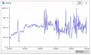 This results in sensor values that are higher or lower than the actual value being read and the erroneous data is called noise. Another kind of noise comes from electrical interference on the cables and connectors that the data are used to communicate the data from the sensor to the microprocessor. It is best to reduce both types of noise at the source, and read in good data, but when that is not possible a software filter can be used to “clean up” or smooth out the data.
Moving average filter
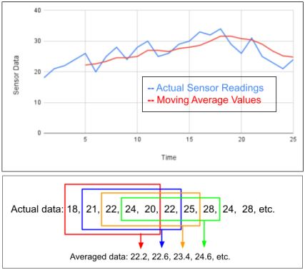
A moving average filter is fairly easy to implement in software, and typically requires past data to be saved and averaged in with the current data. After enough cycles have passed to get an average, the underlying trends in noisy data can be seen. In the code the filter is regularly updated with new data and the oldest data is purged.
An example of a moving average filter that averages the last 5 readings is shown here.
Relative changes vs. absolute changes in data
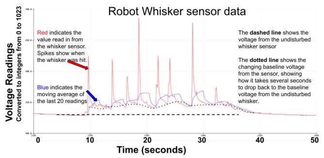
 The moving average filter is particularly useful when it is important to find relative changes in the data, or trends up and down, as is the case with data from the Robot Whisker. In this sensor the conductive grease is encased in stretchable silicone rubber. In its undisturbed state, the grease has a baseline resistance that is stable. When the whisker is deflected the shape of the grease path changes and its resistance changes by a significant amount. However, the when the sensor goes back to its original position, the resistance does not go back to its baseline value, rather it takes several seconds to return the baseline value. In other words, the data trends up and down relatively slowly compared to jumping up and down along with the touch events.
This creates two problems, the first one being that the sensor readings will have to be taken several seconds apart, which might miss some whisker hits. The second problem comes from choosing to take sensor readings quickly; since the sensor resistance would not have gone back to its baseline level, there would be false sensor readings.
The moving average filter solves these problems by allowing for many readings per second, and removing the slowly changing resistance of the undisturbed resistor but still passing the quick changes. See the example in this graph.
Science/Tech Note 5: Circuits using DPDT and SPDT switches to reverse the spin direction of DC motors
Science/Tech Note 5: Circuits using DPDT and SPDT switches to reverse the spin direction of DC motors
Written by Diane Brancazio (dianeb@mit.edu), Revised April 30, 2025
DC motors use Direct Current, that is, current that only flows in 1 direction. DC motors run “forwards” or “backwards” depending on which way the current is flowing. It is easy to get DC power from batteries, and DC motors often have power requirements that correspond to battery sizes, such as 3V, 6V, and 12V.
Motors are often connected directly to power sources and controlled with manual switches. Starting and stopping a motor is easy, and can be done with a Single Pole, Single Throw (SPST) switch that simply opens and closes the circuit. In the SeaPerch robot application, as in many other cases, the user must be able to make the DC motors run forwards, backwards, and stop. The Left and Right thruster motors are each controlled with a Double Pole, Double Throw (DPDT) switch, while the Up/Down thruster motor is controlled with 2 Single Pole, Double Throw (SPDT) switches. The switches are wired such that the current can be stopped or reversed for each motor.
This Science Note presents wiring diagrams and explanations for circuits that use DPDT and SPDT switches to stop and to reverse the spin direction of DC motors.
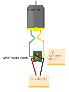
Case 1: Use 1 DPDT toggle switch to control a reversible DC motor.
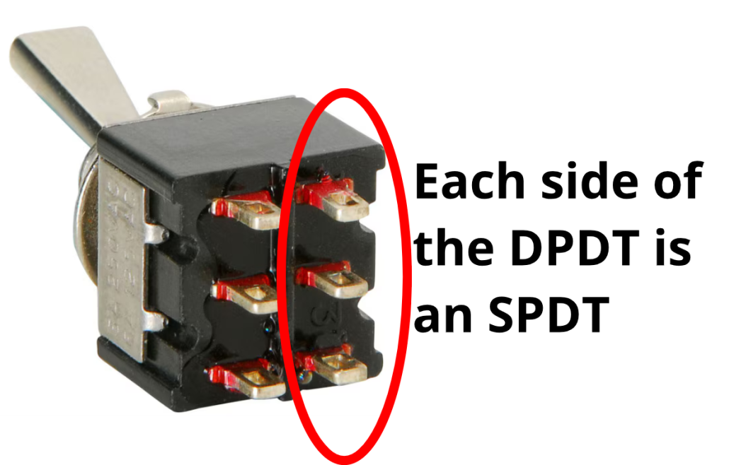
The DPDT switch consists 2 SPDT switches that move together. Each is one side of the switch, with 3 connections: Top, Common, Bottom
When the handle is toggled down, the Common tab is connected to the Top tab. Similarly, when the handle is toggled up, the Common tab is connected to the Bottom tab. 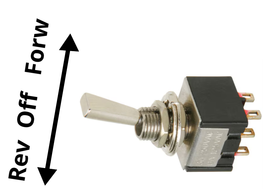
In this wiring configuration the motor is wired to the Common tabs. The Top and Bottom tabs are wired with an “X”, so the 12 V power is reversed between the Top and the Bottom tabs. When the handle is toggled forward, the Common tabs connect to the Bottom tabs, and the motor receives power to spin in the direction that creates forward thrust. When the handle is toggled to reverse, power to the motor is reversed and it created reverse thrust.
It is important that the switches have Momentary contact, and the handles spring back to center when not pushed. In that resting position the Common tabs are not connected to anything and the motor is not powered.
Case 2: Use 2 SPDT toggle switches to control a reversible DC motor. 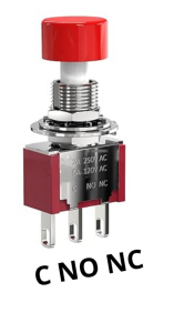
The SPDT switch has 3 connection tabs:
- Common (C)
- Normally Open (NO)
- Normally Closed (NC)
The C tab connects to NC at rest, and to NO when the button is pushed.
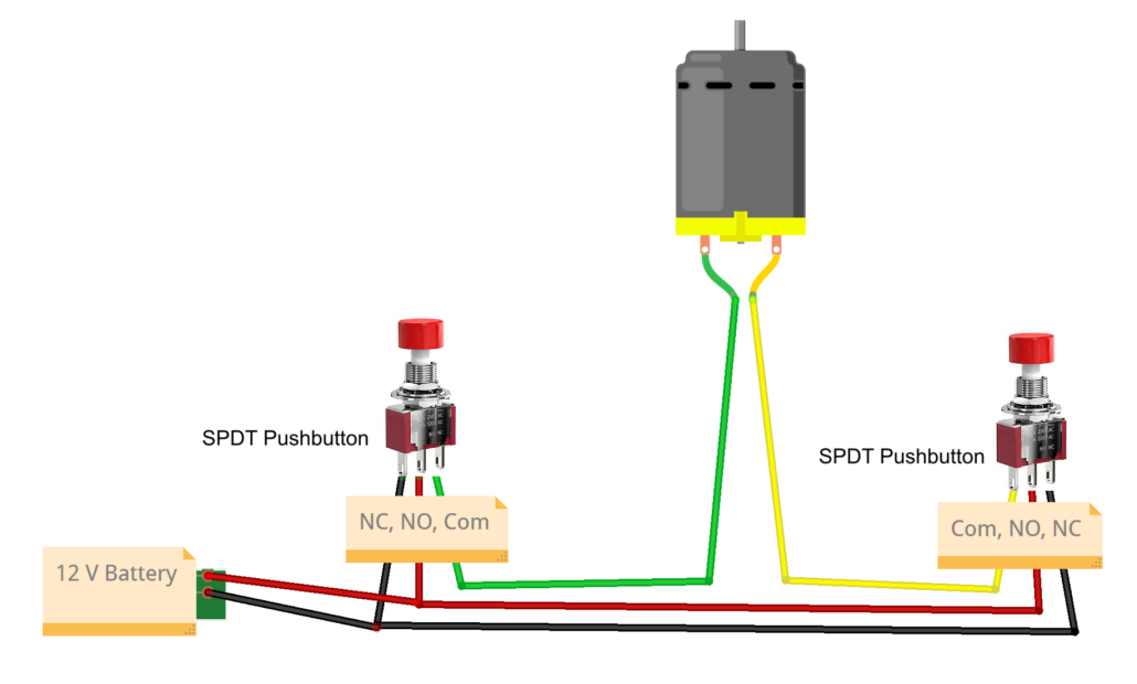
In this wiring configuration, the 2 motor leads are wired to the C tabs of each switch.
The NC tabs on each switch are wired to Ground, and the NO tabs to 12 V.
- When neither switch is pushed, both motor leads are connected to NC, which goes to Ground, and the motor does not spin.
- When only one button is pushed, its C tab connects to NO, which connects one lead of the motor to 12 V, and the motor spins.
- When only the other button is pushed, the other motor lead is connected to 12 V, and the motor spins in the opposite direction.
- If both switches are pushed, both C tabs connect to 12 V, no current can flow, and the motor does not spin.
It is important that the push button switches have Momentary contact, and the button spring goes back up when not pushed.

Safety: Practice tool safety with an adult and follow directions for materials used in this module (e.g. work in a properly ventilated area, wear safety glasses, long sleeves, and vinyl gloves).

