SEAPERCH II MODULE 1:
Robotic Whisker Sensor
*Updated June 2024
Make your own simple and inexpensive touch sensors that work both in the air and underwater. Flick the whisker sensor and make an LED (light-emitting diode) light up on a remote display.
The sensors are completely DIY, from the cast silicone base to the electrical resistive components. On an underwater robot such as the SeaPerch, feedback from the sensors is used to inform the operator of obstacles, and help the operator keep the robot moving in areas where it can move freely. Touch sensors can also be mounted in a navigation course where the robot completes a challenge by touching a specified set of sensors.
How it works
This “robot whisker” is an inexpensive waterproof device that allows the SeaPerch to detect when it has made contact with a physical object. The whisker is a plastic stick mounted in stretchable silicone rubber. Embedded in the rubber is a path of conductive grease that serves as a resistor in a simple circuit. When the whisker is deflected, the rubber deforms and the conductive grease path changes shape, impacting its resistance. An Arduino microcontroller is programmed to detect the change in resistance and inform the operator of this “touch” with a flash of light (or a tone if a speaker is used).
This guide outlines the steps for making a whisker, the attachment to SeaPerch, and the electronic/Arduino connections.
Knowledge and skills needed:
Familiarity with Arduino and wiring on a breadboard
Basic wiring and soldering
Basic hand fabrication
Measuring and handling chemicals
Safety: Practice tool safety and follow directions on any materials used in this module,(e.g., work in a properly ventilated area and wearing safety glasses, long sleeves, and vinyl gloves).
Cost: $100 – $200 (low end when common lab materials are available)
Project tools and materials
| Quantity | Cost | Part Name | Link to Part |
| 1 | $1 | Molds to 3D print (4 parts: Base, Groove, Grease Guide,Top), all reusable | Whisker molds – 3D printable (STL) files |
| 1 | $40 | Ecoflex 00-30 Silicone (Parts A and B) | Ecoflex 00-30 – Super-Soft, Addition Cure Silicone Rubber – Pint Unit (Amazon) |
| 1 | $12 | Mixing Cups, Graduated, 1 ounce, 400/pk | 400 Epoxy Resin Mixing Cups (1 Ounce) Graduated Plastic (Amazon) |
| 1 | $4 | Cotton swabs with plastic stick, 500/pk | Swisspers Swab 500 ct (Amazon) |
| 1 | $17 | Jumbo Wooden Craft Sticks 200/pk | 200 pcs Jumbo Wooden Craft Sticks Pack (Amazon) |
| 1 | $28 | Carbon Conductive Grease, tube. MG Chemicals | MG Chemicals – 846-80G Carbon Conductive Grease, 80g Tube: Automotive Anti Seize Lubricants: Amazon.com: Industrial & Scientific (Amazon) |
| 1 | $15 | Hook up Wire, Stranded, 24 AWG PVC insulation, 6 Colors 32.8 feet each | CBAZY Hook up Wire Kit (Amazon) |
| 1 | $12 | 24 AWG wire, silicone insulation, stranded (this is softer and more flexible than the standard PVC insulation wire). | BNTECHGO 24 Gauge Silicone Wire Kit 7 Color Each 25 ft Flexible 24 AWG Stranded Tinned Copper Wire (Amazon) |
| 1 | $10 | 25ft Ethernet Cable, or similar multi-conductor cable, 2 conductors per whisker. Old cables can be repurposed. | Use this page for reference: https://www.mcmaster.com/communication-cable/ethernet-cable-8/ |
| 1 | $30 | Multimeter to measure resistance | Such as: Crenova MS8233D Auto-Ranging Digital Multimeter Voltmeter Ohm Volt Amp Tester with Backlight LCD Display Test Leads (Amazon) |
| 2 | $6 | Vinyl gloves, disposable, latex-free, 100/box (do not use latex) | Such as: ForPro Vinyl Gloves (Amazon) |
| 1 | $15 | Moldable Silicone Putty | Such as: 900 Moldable Silicone Putty – Grey (Amazon) |
| 1 | $15 | Self-fusing silicone tape | Such as: 4 Rolls Self-fusing Silicone Tape 1” X 10-Feet (Amazon) |
General tools and materials
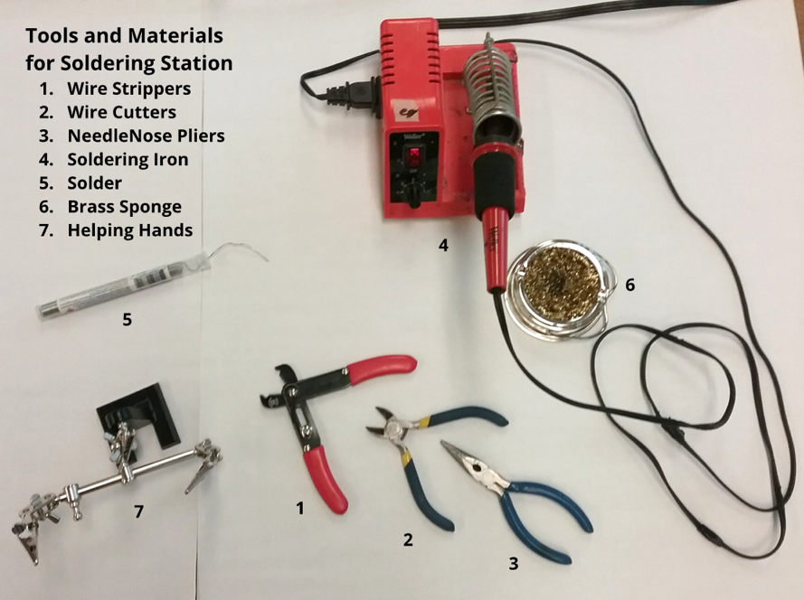
Wiring and Soldering Equipment:
- Wire stripper
- Needle nose pliers
- Wire cutters
- Soldering iron
- Solder
- Brass sponge
- Helping hands soldering aid
- Heat shrink tubing
- Heat gun
Mechanical Fabrication:
- 3D printer and filament
- Utility knife or Exacto knife
- Zip ties
- Hot glue gun
- Vinyl gloves
- Paper towels
Programming and Control:
- Arduino Uno (or similar microcontroller) and programming environment
- Jumper wires
- Solderless breadboard
- Resistor assortment
- LEDs
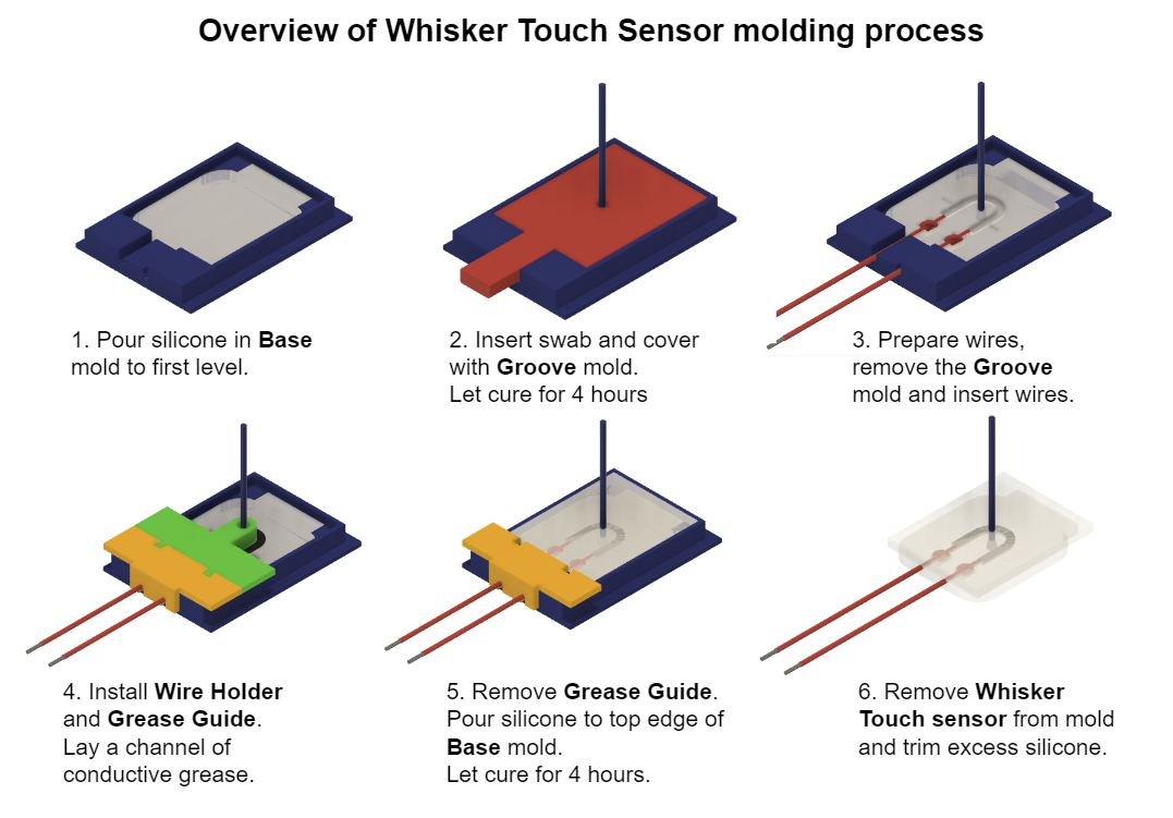
Overview of sensor molding process
Part 1 - Print molds and cast the first layer of silicone rubber
Part 1 – Print molds and cast the first layer of silicone rubber
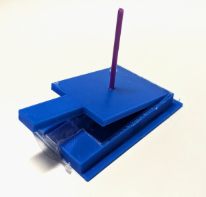
Step 1.1: Print the molds 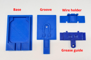
Make the four mold pieces on the 3D printer: the Base, the Groove, the Top, and the Grease Guide. Check that Groove can fit on the Base. Trim any pieces that interfere with a good fit.
Check that Top can fit on the Base. Trim any pieces that interfere with a good fit.
Set aside the Top and Grease Guide for now.
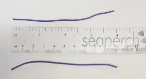
Step 1.2: Prepare the cotton swab (whisker) 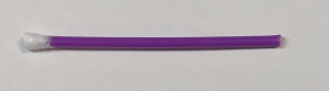
Take one of the cotton swabs (must have a plastic stick, not paper). On one end, use scissors to cut about half of the cotton part off. On the other end, pull off all of the cotton.
Step 1.3: Measure and mix Ecoflex 00-30 silicone rubber 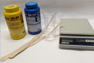
Ecoflex 00-30 has two parts: part A and part B. When these two parts are combined, they cure to form a solid, soft rubber-like material. The ratio of A:B is 1:1, and it can be measured by weight or volume. In either case, use a disposable plastic cup and wear vinyl gloves to protect skin.
Before you mix A and B together, stir parts A and B individually and thoroughly. Use a long sturdy mixing stick that reaches the bottom of the jars so you can scrape the bottom and the sides. The first time you mix the compounds, it could take 10 minutes of rigorous mixing for each jar.
Next you will measure and mix parts A and B in the quantity you need. The volume of silicone needed for the bottom layer of silicone is about 6 ml.
Once mixed you only have 30 minutes before the silicone starts to set. (This is called the “pot life” of the compound). To make one whisker, use one of the methods below. To make multiple whiskers, multiply the amount listed by the number of whiskers desired.
Scale method: Place the plastic cup on the scale and zero the scale. Pour 5 g of part A into the cup, then pour 5 g of part B into the cup. The scale should read 10 g.
Volume method: Pour part A into the cup up to the 5 ml line, then pour part B into the cup up to the 10 ml line.
Mix slowly and thoroughly for 30 – 60 seconds using a clean wood stick, scraping the sides and bottom of the cup. Do not stir quickly as it causes air bubbles to form.
Refer to Science/Tech Notes or EcoFlex instructions for more details.
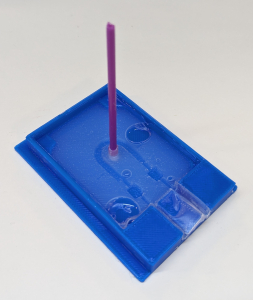
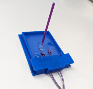
Step 1.4: Pour silicone in the Base mold 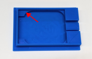
Lay the Base mold on a paper towel and pour silicone up to the first step. Overfilling is okay since any excess silicone will be pushed out by Groove mold.
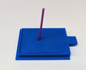
Step 1.5: Add whisker and place Groove mold piece
Insert the whisker (swab) into Groove with the cotton side on the bottom (the horseshoe side of the mold).
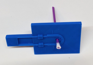
Place the Groove piece on top of the Base mold, and align it.
Apply light downward pressure on the mold piece to push any excess silicone out of the Base mold.
Press down on the top of the plastic swab to ensure that the cotton swab is fully immersed into the silicone.
Leave the assembly in a well-ventilated area for four hours to let the silicone fully cure.
Step 1.6: Prepare the wires
An effective way to secure the wires in the whisker sensor is to tie knots in the wires before the silicone is poured over them in the second cast.
For each whisker, cut two wire pieces from thin stranded hookup wire (22 or 24 AWG, PVC or silicone insulation) about 4” (10 cm) long.
Tie a knot near one end of each wire.
Cut the wire to leave ~ 3/8” (1 cm) wire past the knot. 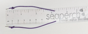
Strip half of that end ~3/16” (½ cm).
Part 2 - Make grease circuit and cast second layer of silicone
Part 2 – Make grease circuit and cast second layer of silicone
Step 2.1: Remove Groove cover and excess silicone
After the first cast is cured, remove the Groove mold piece by slowly lifting the handle.
Cut or peel off excess silicone so there is a smooth channel for the wires.
There may be air bubbles in the cast silicone but it is not a problem since they can get filled in the second cast.
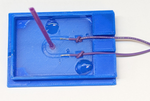
Step 2.2: Insert the wires and retain them with the Wire holder
Lay the wires into the silicone.
Seat the knot into the divot. The ends of the wires should go to the small lines molded into the silicone.
Press the wires all the way into the channels. If the wires do not lay flat, try rotating the wire or take it out and straighten it until it lays flat.
Place the wire holder over the wires to retain the wires.
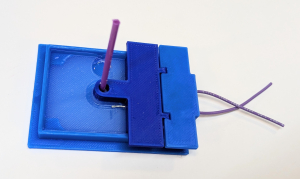
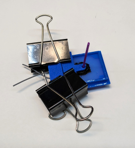
Step 2.3: Install the Grease guide
To install the Grease guide, slide it down over the plastic swab and fit the tabs into the features in the wire holder. Only the stripped parts of the wire should peek out from under the Grease guide. Binder clips may be used to secure the Grease guide and Wire holder.
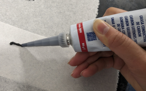
Step 2.4: Prepare the conductive grease
The conductive grease is laid into the groove and connects the two wires. If there are no breaks in the path, it will serve as a resistor. If the grease path changes shape the resistance changes. Deflecting the swab embedded in the silicone changes the shape of the grease path, and therefore the resistance. This change can be detected by an electronic circuit.
Wear vinyl gloves when working with the conductive grease. If it does get on the skin or other surfaces, it can be removed with hand sanitizer or isopropyl alcohol.
Cut the nozzle on the conductive grease so it has an opening of about 2mm. Push a toothpick into the nozzle to make the opening round if needed.
Squeeze the tube gently as you slowly draw the nozzle across a surface. Practice extruding a line of grease in this manner. Enlarge the opening as needed.
If this method does not work well, the grease can be applied to the groove with a small stick.
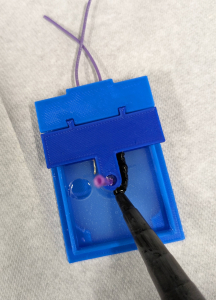
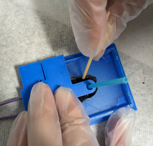
Step 2.5: Apply the conductive grease
The Grease Guide keeps the grease away from the area around the base of the whisker. It is okay if there is a little grease on other parts of the silicone as long as it is not near the swab and can be covered by the next layer of silicone.
Apply the grease in the groove by extruding it from the tube or transferring it with a small stick (popsicle stick, paint brush, toothpick, etc.). Use a toothpick to make sure the grease is filling the groove.
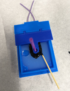
Remove the Grease Guide and check the grease application. The grease should be level with the silicone or slightly higher. Make sure the entire exposed part of the wire is fully covered in grease. If the wires poke up while spreading the grease, push them back down with the stick.
Step 2.6: Repeat Step 1.3: Measure and mix Ecoflex 00-30 silicone rubber
The volume of silicone needed for the top layer of silicone is about 6 ml, the same as for the bottom layer.
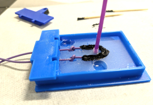
Step 2.7: our upper layer of silicone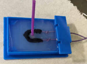
Place the Base mold (with first layer, grease, and wires) on a paper towel on a flat surface.
Pour silicone up to the second cast level/step in the Base mold, over the grease and wires. Overfilling is okay. Leave the assembly in a well-ventilated area for four hours to let the silicone fully cure.
Step 2.8: Extract the whisker sensor and remove excess silicone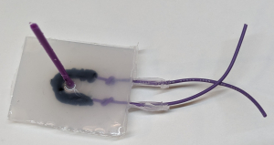
Once the second cast is set, remove the Wire holder and carefully peel up the edges of the silicone rubber. After a bit of peeling, the whisker assembly should come free out of the Base mold. If it is very difficult, use a utility or craft knife to cut along the edges of the silicone rubber base. Lift the whisker assembly out of the base mold. Use scissors to trim any excess silicone along the edges.
Part 3 - Test the whisker sensors
Part 3 – Test the whisker sensors
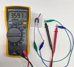
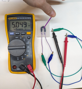
Step 3.1: Find the baseline resistance of the whisker sensor
Strip the ends of the whisker sensor wires about ⅜” (1 cm). Use a multimeter to measure the resistance between the wires. The expected value is between 2 and 8 kΩ.
Deflect the whisker to each side and verify that the resistance changes by about 20% or around 1 kΩ. The resistance changes very quickly and can be hard to read on the multimeter; it will take several tries to get a sense of the resistance changes.
Leave the meter on the wires after deflecting the whisker and notice how the resistance slowly changes back to its original value.
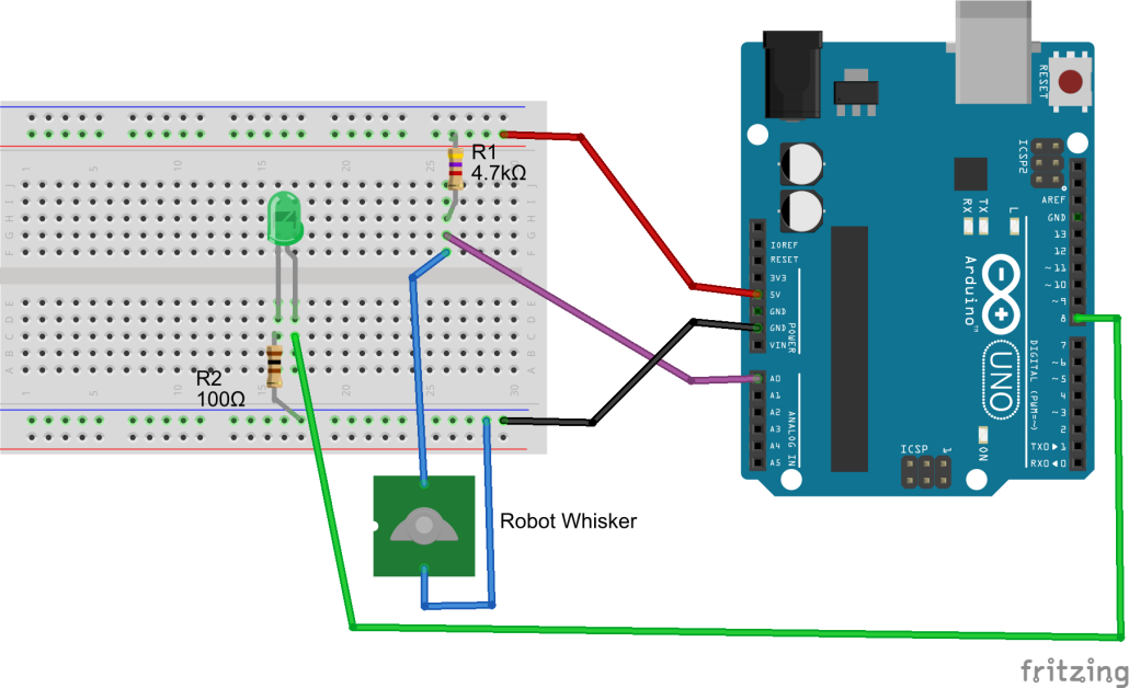
Step 3.2: Create a display and an input circuit for the whisker sensor
The whisker sensor is fundamentally just a variable resistor. To read the change in that resistance, it needs to be used in an input circuit such as a simple voltage divider. Refer to Science/Tech Notes for more information on the voltage divider circuit used for the whisker sensor.
To build the input circuit, select a resistor that is about the same resistance as the whisker sensor in its undisturbed state, as determined in the previous step. In the example, the resistance chosen is 4.7 kΩ.
Use an LED to indicate a whisker touch and to check that the system is functioning appropriately.
Build the circuit shown here to test one whisker sensor. 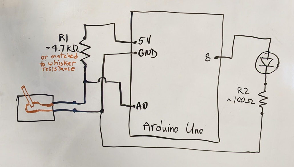
Components:
- Whisker sensor
- Arduino Uno
- Solderless breadboard
- LED
- Resistor, ~100 Ω
- Resistor, ~4.7 kΩ
Connections:
- The (+) end of the LED is connected to a digital pin (pin 8 in this example)
- The (-) end of the LED is connected to a resistor of ~100 Ω
- The other end of the resistor is connected to GND
- Make a voltage divider circuit with the 4.7 kΩ and the whisker sensor as shown
- Connect the sensor reading pin to an analog pin (pin A0 in this example)
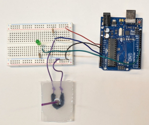
Step 3.3: Test the whisker sensor in air
Connect the whisker sensor and the Arduino and use this sample code to test the whisker sensor: Whisker_Sensor_Test2024.ino.
To test the whisker, deflect it to any side, as if the robot were brushing by an object. Also try flicking it quickly. See this video for a demonstration: WhiskerDemo
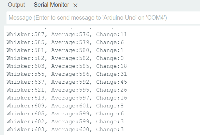
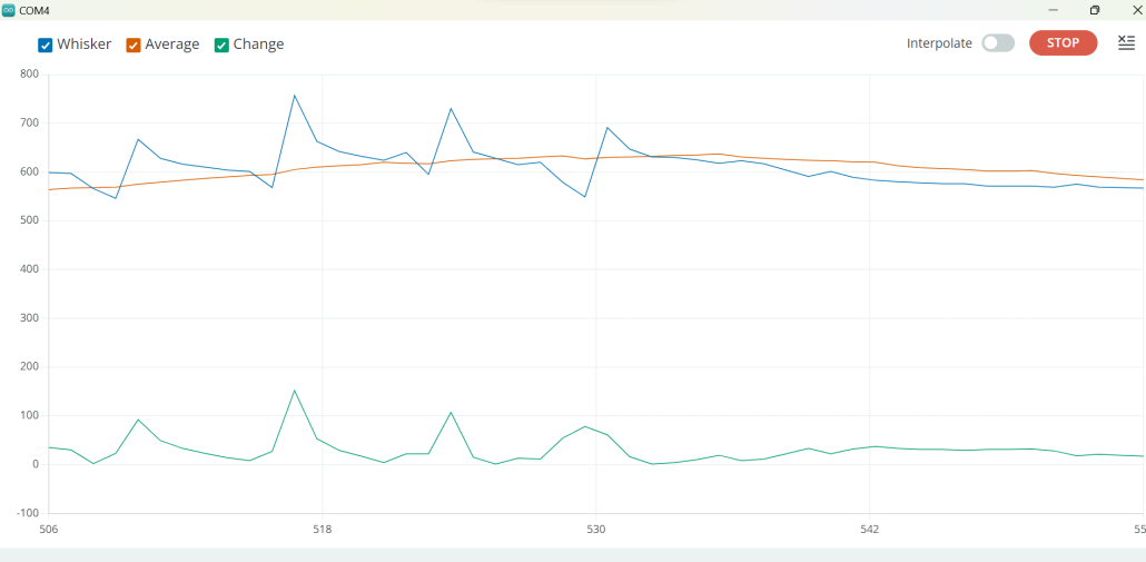
Open the Serial Monitor or the Serial Plotter on the Arduino IDE to see the whisker sensor data as it comes in.
Ways to fix or improve performance:
- Modify the sensitivity of the whisker by changing the value of the variable “bigChange” in the code.
- Use a different resistor (R1) in the voltage divider circuit; one that is closer to the value of your whisker sensor when not deflected
- Watch the values on the Arduino Serial Monitor or Serial Plotter to better understand the problem.
Part 4 - Test whisker(s) underwater
Part 4 – Test whisker(s) underwater
Step 4.1: Create multiple whiskers and an underwater test environment
The Whiskers sensors are designed to work underwater or on land, in any direction.
The test structure used in this guide was made out of PVC pipe (like the SeaPerch) and instrumented with whiskers on top and bottom, left and right. The underwater environment could be a fish tank, a pool, or a deep sink.
Figure out the length of cable from the test structure to the input circuit and LED display and cut a piece of cable about 20” (50 cm) longer.
Step 4.2: Create a long cable for the whisker sensor(s)
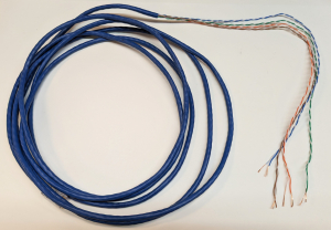
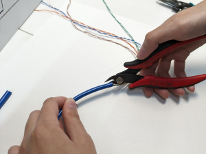
Attach the sensors to a longer cable so they can be used underwater. Ethernet cable with four pairs of wires is convenient for four whiskers. Other options are ribbon cable or individual wires.
Obtain a length of multi-conductor cable that suits the application. If using ethernet cable, cut back the outer covering about 16” (40 cm). Use one pair of wires for each whisker sensor. Strip the ends of the wires about ½” (1.5 cm).
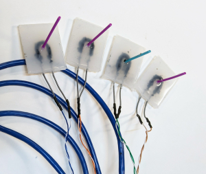
Step 4.3: Connect the Whisker sensor wires to the cable wires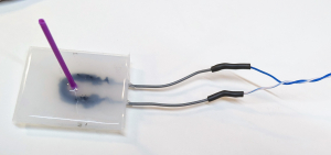
Use soldering tools, make good electrical connections between the whisker sensor wires and the pairs of cable wires. Make note of which wires go to which sensors. Use heat shrink tubing to insulate the connections.
Solder all of the whisker sensors to the cable.
Step 4.4: Make the Arduino end of the cable
The ends of the wires that will go to the Arduino circuit will need jumper pins or solid wire at the ends so they can make connections on a solderless breadboard. Collect jumpers with at least one pin end, two for each whisker.
Half of the jumpers can be the same color since they will all connect to GND. The other jumpers should be different colors, one for each whisker.
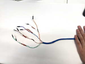
Choose colors that match the cable wires where possible. If some colors do not match, record a color code.
Cut the jumper wires and strip the cut end ~1 cm. Solder the wires to the cable wires. Put heat shrink tubing on each wire to stop the wires from touching each other.
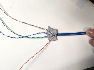
Step 4.5: Waterproof the whisker end of the ethernet cable
When the whisker end of the cable is put underwater, water can “wick” down the insulation of a wire or cable to the circuit board and microcontroller. If using ribbon cable or individual wires, this will not be an issue.
If using an ethernet cable or similar, the wicking can be prevented by sealing the end of the cable with electricians putty and silicone tape.
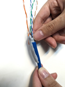
Start by cutting the cable cover open about 1.5” (4 cm).
Next take a piece of electrician’s putty and lay it in the cable cover. Spread out the individual wires.
Squeeze the putty around each wire and tuck it into the cable cover.
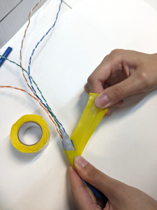
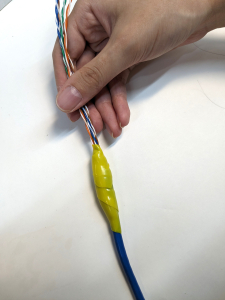
Silicone tape is used to seal the putty and the cable. This tape must be stretched as it is applied, and it sticks to itself permanently. Practice using it as needed.
Cut off a 6” (15 cm) piece of silicone tape and keep it straight while peeling off the clear plastic backing.
Tightly wrap silicone tape around the putty and the end of the cable insulation.
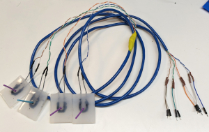
This image shows a completed cable with 4 whisker sensors.
Step 4.6: Create a display and input circuit for 4 whisker sensors
Expand the input circuit and LED display made in Step 3.2 to accommodate 4 whisker sensors. This can easily be done with one Arduino Uno and a small breadboard.
The Arduino code for this circuit can be downloaded here: Whisker_Sensor_Test_4sensors.ino
The diagram below shows four whisker sensors and an LED display.
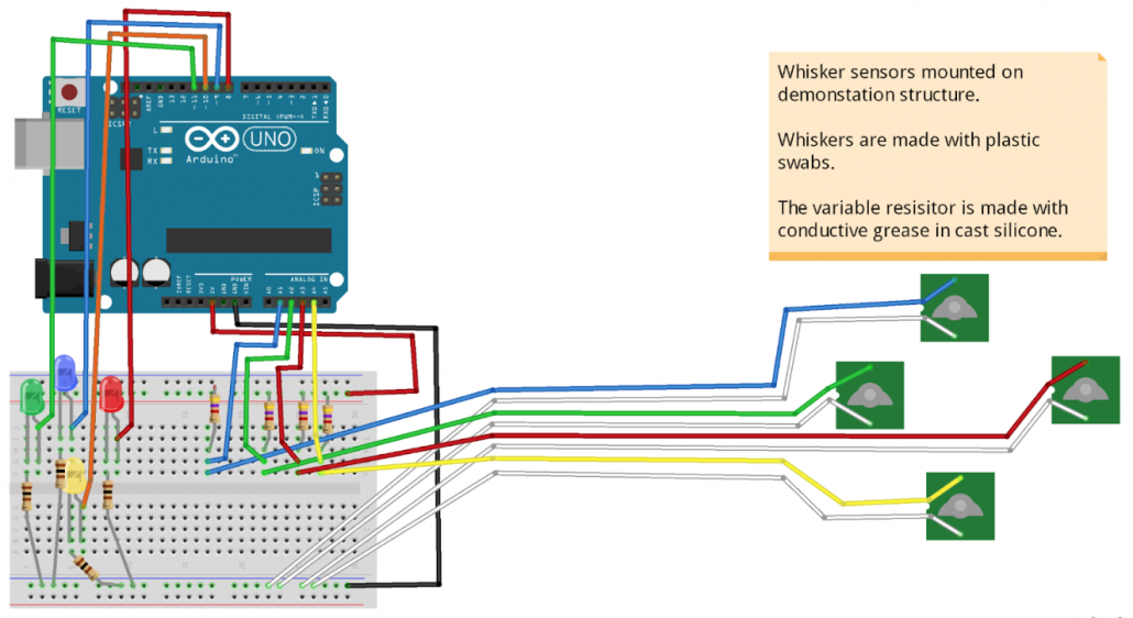
Build the circuit and mount it on a board. Fasten the cable to the display board with zip ties so the wires cannot be pulled out inadvertently.
Step 4.7: Attach the whisker assembly to a test structure

Create a test structure for the sensors, such as the one shown that is made of PVC pipe. The model shown will be used to detect walls or objects to the top, bottom, left, and right. A handle is included so the model can be lowered into a tank or other body of water.
Similar to the SeaPerch underwater robots, holes are drilled in the corner fittings to allow air out when the structure is submerged.
Attach the whisker to the PVC pipe with electrical tape or silicone tape.
Both types of tape require some stretching when applying, more for the silicone tape. Both types of tape adhere better to their own material than to PVC pipe, so make sure the tape strip is long enough to go around the pipe and overlap itself. Silicone tape typically comes 1” wide and can be cut down the middle to make ½” strips.
Place the whisker assembly flat on the PVC pipe and fasten each short end of the whisker onto the PVC pipe. Keep the tape away from the grease channel and do not over tighten the tape to the point where the whisker sensor body is crushed.
Secure the cable to the test structure with tape or zip ties.
Neatly coil or wrap the excess wires and fasten them to the frame with zip ties or tape.

Step 4.8: Test the whisker sensor(s) underwater
See this video of the example test: WhiskerDemo
Now add the Robot Whiskers to a SeaPerch and have
fun experimenting and exploring underwater.

Safety: Practice tool safety with an adult and follow directions for materials used in this module (e.g. work in a properly ventilated area, wear safety glasses, long sleeves, and vinyl gloves).
Cost: $100 – $200 (low end when common lab materials are available)
Knowledge and skills needed:
- Familiarity with Arduino and wiring on a breadboard
- Basic wiring and soldering
- Basic hand fabrication
- Measuring and handling chemicals
