SEAPERCH II MODULE 2:
Pressure (Depth) and Temperature Sensor
Make a simple and inexpensive device that reports absolute pressure and temperature both in the air and underwater.
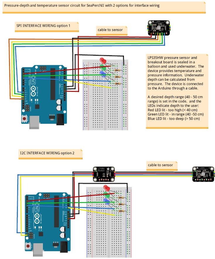
Depth underwater is easily calculated from pressure, so a sensor attached to a SeaPerch robot can tell you its depth. Find out if your robot is too high, too low, or just right by lighting LEDs for each case. Use this information to navigate at a specific depth or to take temperature measurements at different levels. In this build guide the Adafruit LPS35HW Pressure sensor is waterproofed and tethered to an Arduino Uno microcontroller that is in a dry location.
More Videos:
How it works
The sensor module (Adafruit LPS35HW) is sealed in a balloon, then protected by a simple housing so it can be deployed safely underwater. The balloon is not inflated, but has a small amount of air in it because it is loose around the sensor module. That air is compressed by hydrostatic pressure (the pressure created by water) when the sensor is situated underwater. The hydrostatic pressure is proportional to the depth measured from the surface, and through simple calculations, underwater depth of the sensor can be determined. The housing is meant to fill with water and can be made from a recycled bottle or spare piece of PVC pipe – its function is just to provide a protective shell for the electronics and balloon.
How to get the data
The sensor is connected by cable to an Arduino microcontroller. Sample code, which reads the pressure and temperature, calculates depth, and displays the readings in text, graph, or on an LED display, is provided. Other options are to save the data using a data storage card/device or to display the data on a digital readout. These are both common methods that users can research and design on their own.
Materials
| Qty | Cost | Part name | Link |
| 1 | $12.50 | Adafruit LPS35HW Water Resistant Pressure Sensor | https:learn.adafruit.com/lps35hw-water-resistant-pressure-sensor |
| 1 roll | $12 | Rescue Tape/Self-fusing Silicone tape | https:www.amazon.com/Rescue-Tape-CECOMINOD019585-RT1000201206USCO/dp/B000ZTM72U/ |
| 1 bag | $9 | 12-inch balloon | https:www.amazon.com/gp/product/B0B52PNWPP |
| 1 pack | $20 | Electrical putty or Duct Sealing Putty | https:www.amazon.com/3M-Scotchfil-Electrical-Insulation-Putty/dp/B001A5MBBU https:rainbowtech.net/products/duct-seal-putty/ |
| SPI interface between Arduino and LPS35HW Pressure Sensor | |||
| 15’ – 30+’ as you need | $11 | Cable with 6 or more wires inside, 24 AWG
May be ethernet cable or ribbon cable |
https:www.amazon.com/RGBWW-Strip-Extension-Ribbon-Lighting/dp/B08P23M8VG/ |
| I2C interface between Arduino and LPS35HW Pressure Sensor | |||
| 15’ – 30+’ as you need | $11 | Cable with 4 or more wires inside, 24 AWG
May be ethernet cable or ribbon cable |
https:www.amazon.com/RGBWW-Strip-Extension-Ribbon-Lighting/dp/B08P23M8VG/ |
| 1 | $1 | I2C connector wire with jumper ends | https:www.adafruit.com/product/4209 |
| 2 | $1.50 | I2C connector cable with STEMMA JST-SH 4-pin connector.
This cable will be cut in half and the wires stripped to make two cables with solder ends. Use any size that is available |
https:www.adafruit.com/product/4401 (200mm) |
| 1 | $7.50 | I2C signal booster for long cables – Adafruit LTC4311 I2C Extender | https:www.adafruit.com/product/4756
https:learn.adafruit.com/adafruit-ltc4311-i2c-extender-active-terminator |
| Housing Method 1 | |||
| 1 | 1-¼” PVC Pipe, ~ 6” piece | ||
| 1 | 1-¼” PVC Pipe Cap | ||
| Housing Method 2 | |||
| 1 | $0 | Pill Bottle or other small plastic bottle with:
Diameter > 1.25” Length > 4” |
|
General tools and materials
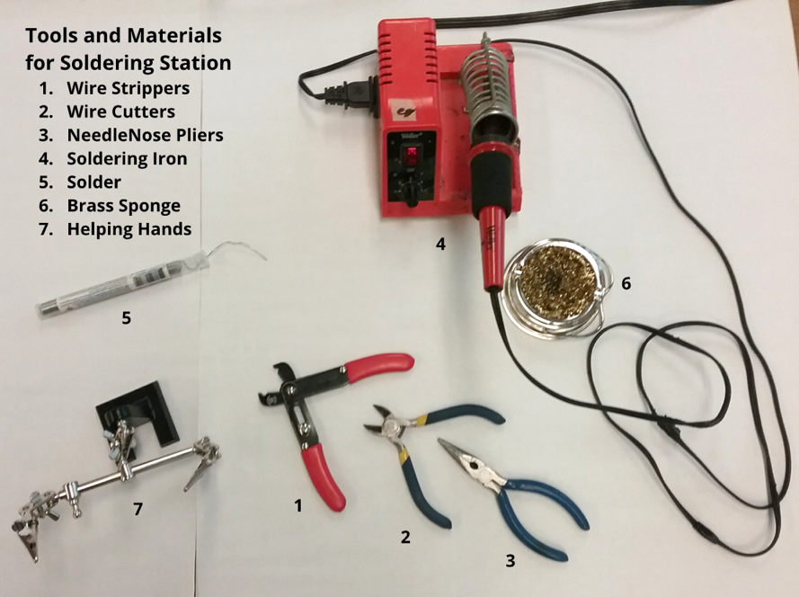
Wiring and Soldering Equipment:
- Wire stripper
- Needle nose pliers
- Wire cutters
- Soldering iron
- Solder
- Brass sponge
- Helping hands
- Heat shrink tubing
- Heat gun
- Electrical tape
Mechanical Fabrication:
- Utility knife or Exacto knife
- Zip ties
- Drill and drill bits
- PVC pipe cutter or handsaw
Programming and Control:
- Arduino Uno (or similar microcontroller) and programming environment
- Jumper wires
- Solderless breadboard
- Resistor assortment
- LEDs
Part 1: Connect the components and test on a long cable
Step 1.1: Choose a connection option and test the sensor on a short cable
Choose one of the following communication protocols: SPI (Serial Peripheral Interface) or an I2C (Inter-Integrated Circuit, aka I2C and IIC). I2C is recommended here because it is rated to go longer distances, uses fewer wires, and can be easily connected to this board with the STEMMA-QT 4-pin cable and connector. There is also an I2C booster chip available from Adafruit. The SPI interface may also be used; it requires fewer specialized parts but more wires.
Choose a protocol, gather the parts, and connect the LPS35HW to the Arduino. Test it out by following the tutorial at learn.adafruit.com/lps35hw-water-resistant-pressure-sensor/arduino.
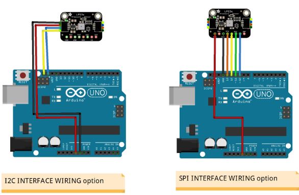
Connections:
| For Serial Peripheral Interface (SPI)
Sensor pins → Arduino pins |
For I2C interface, with discrete wires or with a JST-SH 4-pin connector to the header on the sensor board
Sensor pins → Arduino pins |
| Vin – power in → 5V
GND – ground → GND SCK – SPI Clock pin → 13 SDO (MISO) – Serial Data Out / Microcontroller In Sensor Out → 12 SDI (MOSI) – Serial Data In / Microcontroller Out → 11 CS – Chip Select pin → 10 |
Vin (Red wire on JST-SH) – power in → to 5V
GND (Black wire on JST-SH) – ground → GND SCK (Yellow wire on JST-SH) – the I2C clock pin, → A5 or SCL (near AREF) SDI (Blue wire on JST-SH) – the I2C data pin, → A5 or SDA (near AREF) SDO and CS pins are not needed in I2C protocol |
Use the sample code provided in the Adafruit tutorial or use the code provided here that also converts pressure to depth pressureDepthSensorTest.ino Modify the code in the setup () section as needed for the chosen communication protocol.
Continue here if using the I2C interface. Jump ahead to Step 1.6 if using SPI
Step 1.2: Prepare the I2C cable ends
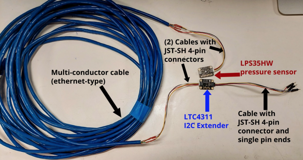
For distances greater than about 4 ft (1.5 m), the signal will need to be boosted electronically. For this the I2C interface is best and the booster chip can be added as shown in this diagram and described below.
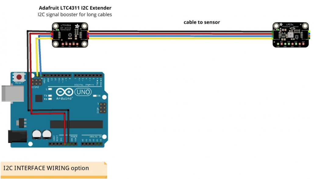
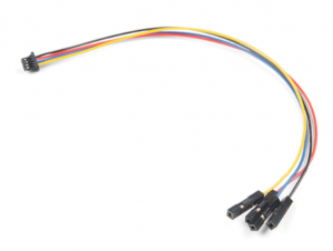 If using the I2C booster chip (LTC4311) get the cable with a JST-SH 4-pin connector on one end and separate pins on the other (such as adafruit.com/product/4209).
For the connection to the long cable, get a cable with a JST-SH 4-pin connectors on both ends such as (adafruit.com/product/5384).
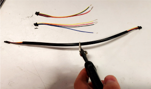 Cut it in half, and strip the wires on the cut side. Both halves will be used.
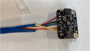
Step 1.3: Assemble the long I2C cable and the sensor
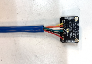
Get the desired length of cable with 4 conductors, (ribbon, cylindrical, or loose wires).
Strip the wires on both ends for soldering.
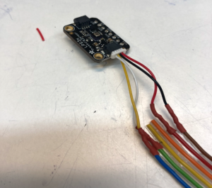 Wires can be soldered directly to the sensor board, but it is better to use the small cable with the JST-SH 4-pin connector if it is available.
Solder the long cable wires to the sensor board or to the connection cable.
Use heat shrink tubing to keep the connections from touching each other.
Record the color code from the sensor to the cable on a table such as this:
| Connection on sensor board | Jumper color on JST-SH connector | Cable color | Jumper color to Arduino |
| Vin | Red | ||
| GND | Black | ||
| SCK | Yellow | ||
| SDI | Blue | ||
| SDO and CS pins are not connected | —– | —– |
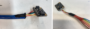
Step 1.4: Add the I2C booster chip to the cable
Collect the remaining two short cables from Step 1.2.
Solder the one with the stripped ends to the long cable following the color code used on the other end and recorded on the table. Put heat shrink tubing on each wire to stop the wires from touching each other.
Connect the I2C booster chip to the other components as shown:
Step 1.5: Connect to the Arduino and test the sensor in air
As done in Step 1.1, Test and confirm the functionality using the sample code provided in the Adafruit tutorial or the code provided here that also converts pressure to depth (pressureDepthSensorTest.ino). Modify the code in the setup () section as needed for the chosen communication protocol.
When the system is functional, go on to Part 2. The next steps are for connecting the sensor over the SPI communication protocol.
Step 1.6: Assemble the long SPI cable and the sensor
Get the desired length of cable with 6 conductors.
Remove about 2” (5 cm) of the cable housing from each end.
Strip the wires on on one end of the cable only about 3 mm (⅛”).
Solder the pressure sensor to one end of the cable wires. Record the color code from the sensor to the cable on a table such as this:
| Sensor board | Cable color | Jumper color to Arduino |
| Vin | ||
| GND | ||
| SCK | ||
| SDO | ||
| SDI | ||
| CS |
Step 1.7: Make the Arduino end of cable
Collect 6 jumpers with at least 1 pin end. Choose colors that match the cable wires as possible.
If some colors do not match, record a color code on the table. Cut the jumper wires in the middle and strip the cut end about 1 cm (⅜”).
Strip the cable wires about 1 cm as well.
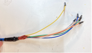 Solder the jumper wires to the cable wires. Put heat shrink tubing on each wire to stop the wires from touching each other. As needed, keep the wires in place with electrical tape.
Step 1.8: Connect to the Arduino and test the sensor in air
As done in Step 1.1, Test and confirm the functionality using the sample code provided in the Adafruit tutorial or the code provided here that also converts pressure to depth (pressureDepthSensorTest.ino). Modify the code in the setup () section as needed for the chosen communication protocol.
Part 2 - Sensor-cable-balloon assembly (Resume here for both SPI + I2C interface connections)
Step 2.1: Make a section of the cable wires solid and watertight
 Up from the sensor about 2 to 4 inches (5 – 10 cm), make a section of the cable solid and watertight. This is where the balloon will seal to the cable, making a sealed air chamber for the sensor.
If a cable with an outer covering is used, slice the cable open a little bit so it is easier to seal the inside of the cable. If a flat ribbon cable is used, roll it to make a solid cylindrical section.
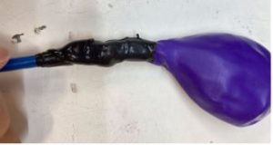
 The electrical putty should be in between each individual wire to ensure a complete seal. Squeeze the end of the cable that wraps around the putty to make sure that all cracks are covered. Add more if needed.
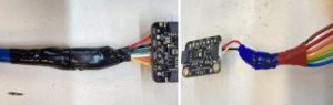 Wrap the rescue tape around the electrical putty to hold it in place. Stretch the tape lightly while wrapping it around for a tighter and more secure wrap. No electrical putty should be exposed after the wrap.
Step 2.2: Insert pressure sensor into balloon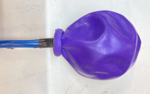
Roll back the neck of the balloon, stretch the opening, and insert the pressure sensor into the balloon.
Keep the neck rolled up for the next step.
Step 2.3: Seal balloon to cable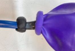
Wrap electrical putty around the cable close to the balloon.
Unroll the balloon neck and wrap around the electrical putty. Squeeze the balloon neck lightly to ensure it is tightly sealed to the electrical putty.
Squeeze the balloon lightly to check for any leaks. 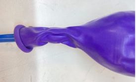
Wrap the balloon neck with rescue tape tightly to make the final seal between the balloon and the cable. The opening of the balloon should be completely covered with tape.
Part 3: Make a protective housing for the balloon and sensor
The housing is a protective shell for the electronics and balloon. It is meant to fill with water and sink. Material options for the housing include recycled bottles and spare pieces of PVC pipe. 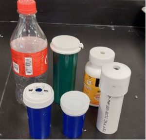
The interior dimensions of the housing should be:
- Length: 4” (10 cm) or longer
- Diameter: 1 ¼” (3 cm) or greater
PVC pipe matches the construction of the SeaPerch robot, while recycled plastic bottles are easy to find. Instructions for the PVC pipe method and the plastic bottle method are included here.
Method 1 – PVC pipe
Step 3.1: Cut PVC pipe
Cut a 1-¼” inch PVC pipe with a pipe cutter.
The length should be approximately the same as the balloon and the tape, 4” (10 cm) or longer.
Step 3.2: Drill PVC cap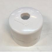
Drill a hole in the middle of the PVC cap.
The hole should be big enough that the cable can slide through it and small enough that the pressure sensor will not come out.
Step 3.3: Assemble and fasten in place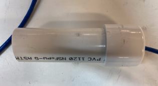
Pass the cable end with the jumpers through the PVC cap, from the inside. Twist the cap on to the PVC pipe. The whole balloon should be hidden inside the pipe.
Wrap a cable tie around the cable to keep the cable from slipping out.
The finished product should not be positively buoyant.
Method 2 – Plastic bottle
Step 3.1: Drill holes in the pill bottle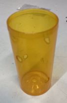
Drill 4 holes on the sides of the plastic bottle. Make the holes large enough so the bottle fills quickly when in the water, 3/16” (1 cm) or larger.
Drill 1 or 2 more holes in the bottom of the bottle.
Step 3.2: Drill a hole in the bottle cap
Drill a hole in the cap. 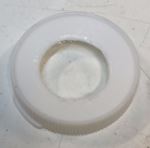 The hole should be big enough that the cable can slide through it and small enough that the pressure sensor will not come out.
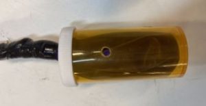
Step 3.3: Assemble and fasten in place
Pass the cable through the cap hole (the end with the jumpers) and put the cap on the bottle. The whole balloon should be hidden inside the pipe. The finished product should not be positively buoyant.
Part 4: Test the system
Step 4.1: Create a display to show depth
Choose a desired range for the depth of the sensor and create a simple display.
In this example the desired range is 40 cm – 50 cm.
The red LED indicates the pressure sensor is too high, the green LED indicates the sensor is within range, and the Blue LED indicates the sensor is too low.
Connections to LEDs:
- The (+) end of the LED is connected to a digital pin. (Red – pin 2, Green – pin 3, Blue – pin 4)
- The (-) end of each LED is connected to a resistor of ~100 Ω
- The other end of each resistor is connected to GND
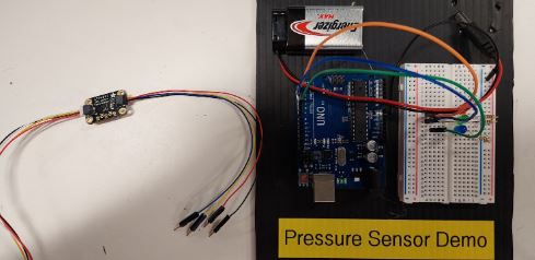
Step 4.2: Connect the sensor to the Arduino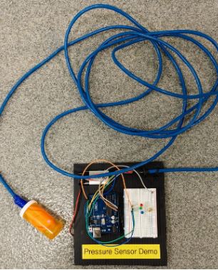
Connect the cable wires to the Arduino. Fasten the cable to display board with zip ties so the wires cannot be inadvertently pulled out.
Wiring for both the SPI and the I2C interface is shown here.
Components:
- Pressure sensor (assembled in balloon) Adafruit LPS35HW
- I2C booster Adafruit LTC4311 I2C Extender (if needed)
- I2C connector cable with STEMMA JST-SH 4-pin connector (if needed)
- Arduino Uno
- Solderless breadboard
- LEDs
- Resistors, ~100 Ω
| Connections and wiring notes for Serial Peripheral Interface (SPI)
Sensor pins → Arduino pins |
Connections for I2C interface, with discrete wires or with a JST-SH 4-pin connector to the STEMMA QT header on the sensor board
Sensor pins → Arduino pins |
| Vin – power in → 5V
GND – ground → GND SCK – SPI Clock pin → 13 SDO (MISO) – Serial Data Out / Microcontroller In Sensor Out → 12 SDI (MOSI) – Serial Data In / Microcontroller Out → 11 CS – Chip Select pin → 10 |
Vin (Red wire on JST-SH) – power in → to 5V
GND (Black wire on JST-SH) – ground → GND SCK (Yellow wire on JST-SH) – the I2C clock pin, → A5 or SCL (near AREF) SDI (Blue wire on JST-SH) – the I2C data pin, → A5 or SDA (near AREF) SDO and CS pins are not needed in I2C protocol |
Step 4.3: Test the sensor underwater and display results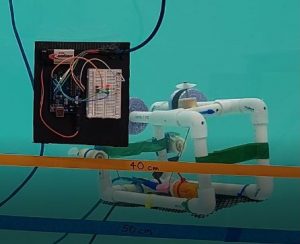
Attach the pressure sensor to the SeaPerch with a couple of cable ties. Check that the housing fills easily with water and does not hold excess air as that would affect the buoyancy of the SeaPerch.
Use, or adapt, this code to display depth and control the LEDs: pressureDepthSensorTest.ino.
What’s in the code:
This program reads in the pressure and converts it to depth underwater in cm or ft.
The conversion equation comes from the Hydrostatic Water Pressure Formula P = ⍴gh (⍴ is the Greek letter rho, lowercase).
- P is the pressure of a fluid at a depth in water
- ⍴ is the density of the fluid (997.05 kg/m^3 for freshwater, and 1023.6 kg/m^3 for saltwater), and h is the column of water above
- g is the acceleration of gravity (9.807 m/s^2)
- h is the height of the fluid column
Solving for h, the equation is h = P/(⍴g).
Calculated through, it is h = P / 9778 (freshwater), and h = P / 10038 (saltwater).
Change the value in the code as appropriate.
For accurate readings of depth underwater, submerge the sensor at the very top of the water and hit the Reset button on the Arduino.

Safety: Practice tool safety with an adult and follow directions for materials used in this module (e.g. work in a properly ventilated area, wear safety glasses, long sleeves, and vinyl gloves).
Cost: $75 (or less if repurposing other materials)
Knowledge and skills needed:
- Familiarity with Arduino and wiring on a breadboard
- Basic wiring and soldering
